Blog

Explore the KKPCB Blog for the latest PCB manufacturing and assembly news, industry insights, expert tips, and technology trends, helping you stay informed and optimize your electronics projects.
How to Keep a High-Voltage Pulser from Polluting an Ultrasound PCB Receive Path

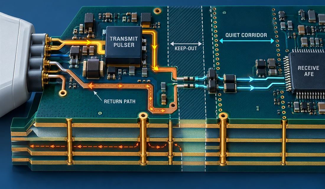
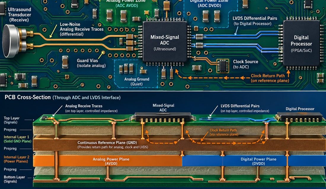
Ultrasound PCB partitioning becomes difficult when the transmit pulser and the receive AFE share a small probe-side area. During a transmit event, a short high-voltage pulse can create a large local current loop, while the receive channel is trying to preserve a much smaller echo signal. If the board treats those two functions as ordinary...

When Ultrasound Echoes Become Layout Noise: A Low-Noise Ultrasound PCB Release Plan

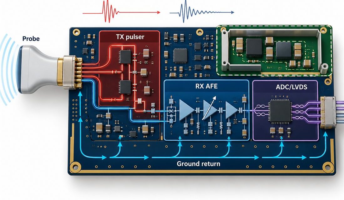
Ultrasound PCB design fails in a very specific way: the image can look acceptable on a bench and then lose contrast when transmit voltage, receive gain, clock activity, and patient-interface cabling are present at the same time. The difficult part is not choosing an expensive AFE; it is preserving the receive signal while the board...

Medical PCB: 5 Rigid-Flex Checks for Wearable Devices

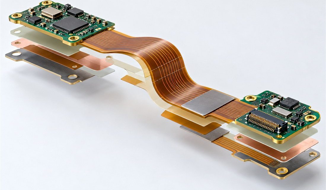
Medical PCB rigid-flex design for a wearable device has to begin with motion, not only with the circuit diagram. The flex section may fold during assembly, bend during use, pass through an enclosure hinge, or absorb a connector transition. Each of those conditions changes the copper pattern, coverlay, stiffener placement, stackup, and assembly sequence. Treating...

Medical PCB: 5 Change-Control Checks to Avoid Revision Gaps

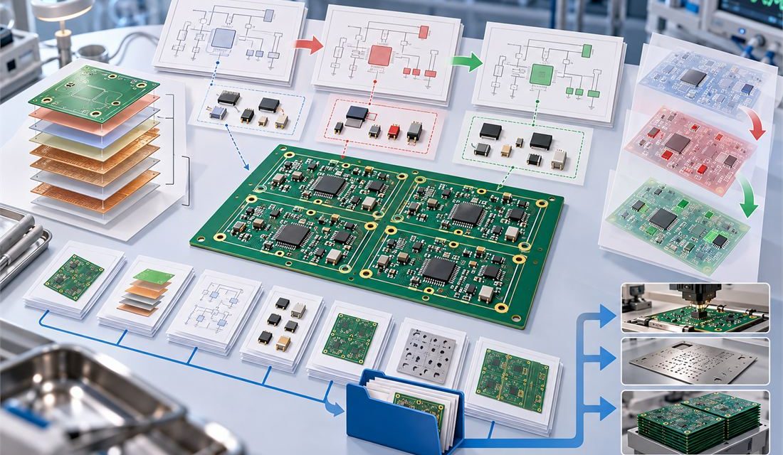
Medical PCB change control becomes fragile when a revision is treated as only a new Gerber archive. A production-ready release is a controlled set of connected information: schematic references, layout data, fabrication drawing, stackup, drill information, material assumptions, assembly outputs, test requirements, approved deviations, and the revision record that explains what changed. If those items...

Medical PCB: 7 Essential Rules to Avoid Layout Noise

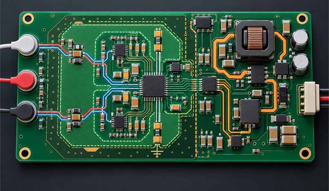
Medical PCB layout for a low-level biopotential front end starts with a simple discipline: treat the sensor input, its reference, and its return path as one small system before placing anything noisy nearby. ECG, EMG, impedance, and other low-amplitude acquisition paths can be affected by switching current, digital edge energy, cable pickup, and unintended return...

Robotics PCB Serviceability: Designing the Board for Repeatable Replacement

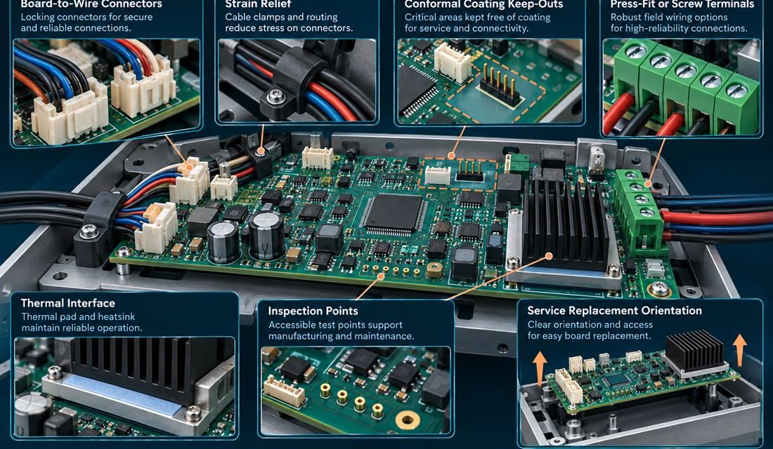
Table of Contents Why serviceability belongs in the PCB release Treat connectors and strain relief as one system Protect thermal and coating interfaces Make inspection repeatable Close the maintenance handoff A robot controller is rarely repaired on a quiet laboratory bench. A technician works inside a cabinet or joint enclosure, disconnects a harness, replaces a...

Robotics PCB Vision and Force Sensing: Keeping Mixed Signals Honest

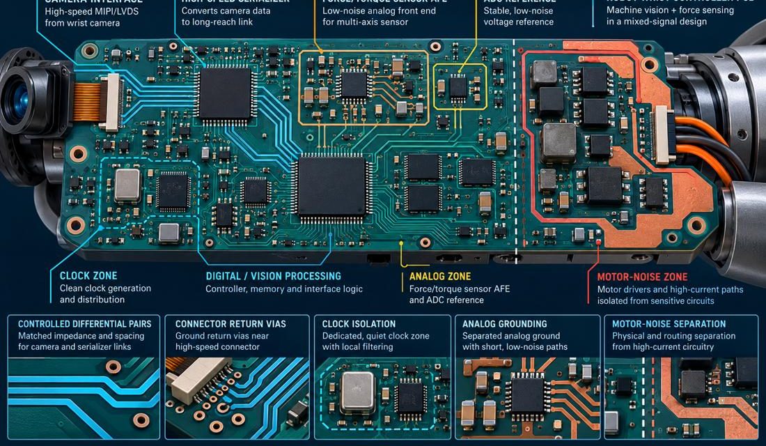
Table of Contents Why vision and force signals fight on one board Partition clocks, analog, and motor noise Protect high-speed launches Calibrate the sensor chain Release a wrist module A robot wrist that combines a camera, a force/torque sensor, and a motor interface has three different definitions of “clean data.” The camera needs controlled differential...

Robotics PCB Safety Isolation: Making the Barrier Manufacturable

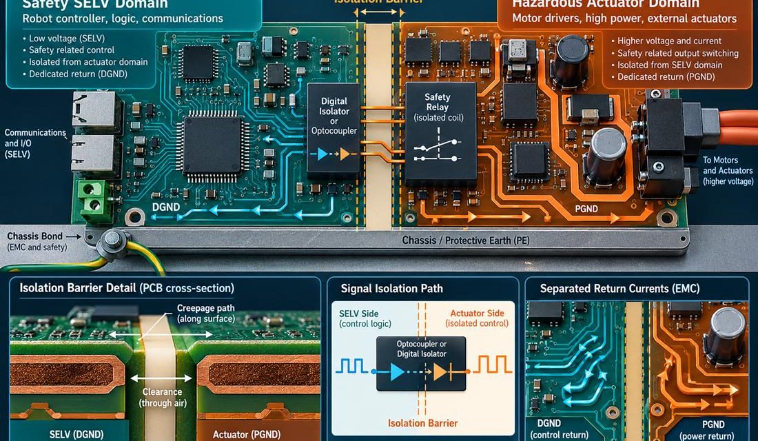
Table of Contents Treat the isolation boundary as a system boundary Turn creepage into layout geometry Keep EMC current out of logic return Verify the fault state Release evidence without overclaiming A robot controller can pass a functional motion test and still carry a dangerous layout ambiguity. The problem appears where low-voltage logic, safety I/O,...

Robotics PCB Encoder Feedback: Keeping A/B/Z Phase Intact

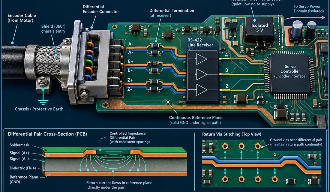
Table of Contents Why encoder faults masquerade as software bugs Keep A/B/Z pairs phase-stable Close the shield and return path Test cable length and temperature Release feedback with evidence When a robot axis occasionally reports a position jump, the first suspect is often firmware. Yet many intermittent encoder faults are created at the connector launch,...