
Table of Contents
When a robot axis occasionally reports a position jump, the first suspect is often firmware. Yet many intermittent encoder faults are created at the connector launch, the differential termination, or the reference-plane transition on the board. A Robotics PCB that receives A/B/Z feedback must preserve phase, common-mode margin, and return continuity while sharing an enclosure with motor switching and long moving cables.
The engineering challenge is not to make one clean waveform on a short bench cable. It is to release an encoder interface that remains interpretable across cable variants, shield handling, temperature, service replacement, and the exact grounding scheme used in the robot joint. The following workflow gives design, manufacturing, and program teams a common review language.
Why encoder faults masquerade as software bugs
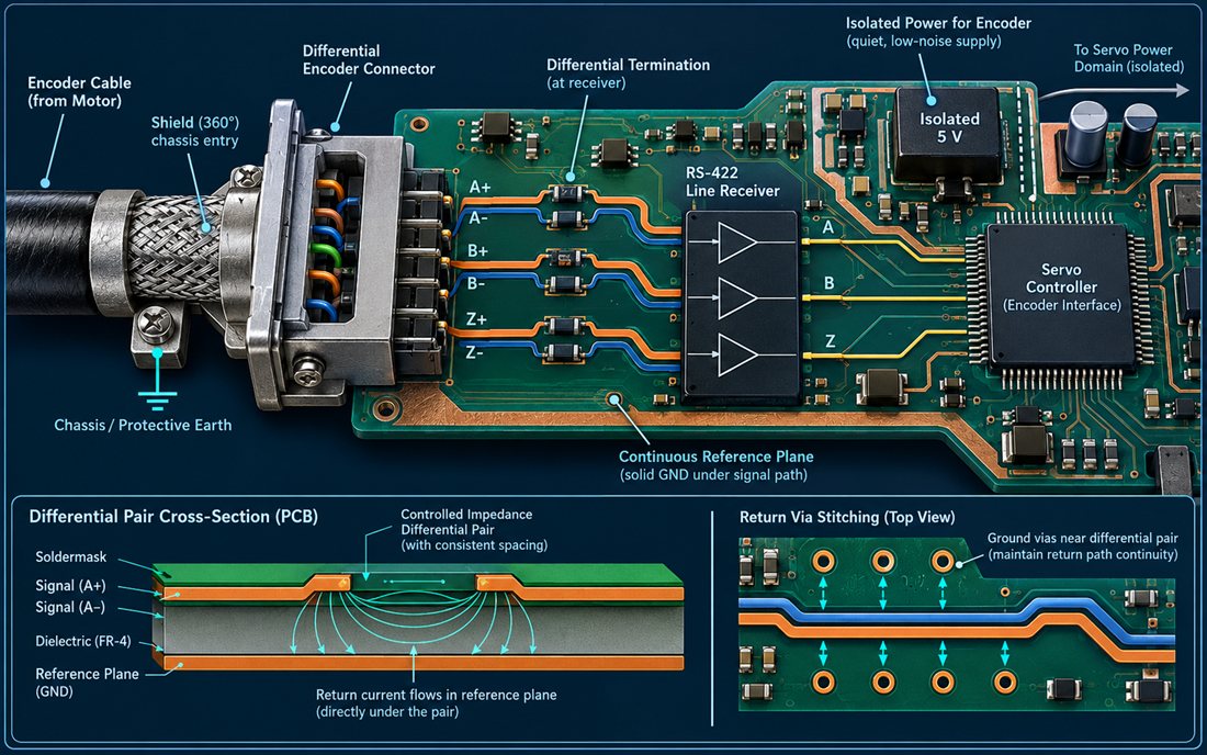
An encoder receiver on a Robotics PCB sees the combined result of source amplitude, cable impedance, termination, connector geometry, reference continuity, and noise coupling. A missed edge can look like a counting error; a false edge can look like a bad motion profile. Start the PCB design review at the motor connector and trace every A+, A−, B+, B−, and index conductor to the receiver. Record where the pair changes layer, where a return via is needed, and where a shield or chassis bond enters the assembly.
For a Robotics PCB used in a collaborative arm, the cable can flex thousands of times and may be replaced by a service technician with a different construction. Specify the electrical interface and the acceptable cable family instead of relying on a connector name alone. A “compatible” cable with a different drain-wire termination can move common-mode current through the signal reference.
Keep A/B/Z pairs phase-stable
Route each differential pair on the Robotics PCB with consistent spacing and a continuous reference. Keep the receiver termination close to the input pins and avoid a via branch that leaves an unterminated stub. When the pair crosses a plane transition, place the return vias next to the signal vias so the return current does not spread into the motor-power region. The geometry belongs in the released high-frequency PCB or controlled-return drawing even if the encoder clock is comparatively slow.
Do not tune A/B length by eye while ignoring the index channel. The index pulse can be narrower and more sensitive to edge distortion than the quadrature channels. Define the receiver threshold, termination option, and polarity in the schematic and test procedure. A small series element may help with ringing, but it must be evaluated with the real cable and receiver input rather than added as a generic fix.
Make the connector launch part of the signal path
The Robotics PCB connector footprint, shield tabs, mounting hardware, and nearby return vias define the launch. A connector pinout that places A+ beside a noisy motor phase can defeat otherwise careful routing. Keep the pair order intuitive for inspection, give the shield a short chassis path, and document whether the connector shell is bonded at the board, at the enclosure, or at both ends. The PCB materials and finished copper construction also affect the repeatability of the controlled geometry.
Close the shield and return path
Robotics PCB shielding is a current-management decision, not a decorative layer. A braid or foil carries common-mode current that must reach chassis without passing through the receiver reference. Place the entry point near the connector, keep the chassis path wide and short, and separate it from the logic return until the system-level EMC strategy defines the bond. If an isolated encoder supply is used, show its capacitance and safety path on the electrical drawing.
Motor-drive switching can couple through air, cable capacitance, or a shared mounting bracket. Use a ground-via fence where it supports the intended return, but do not surround the pair with disconnected copper islands. The PCB manufacturing package should call out the via pattern, annular ring, solder-mask opening, and connector coplanarity so the intended path survives fabrication and assembly.
Test cable length and temperature
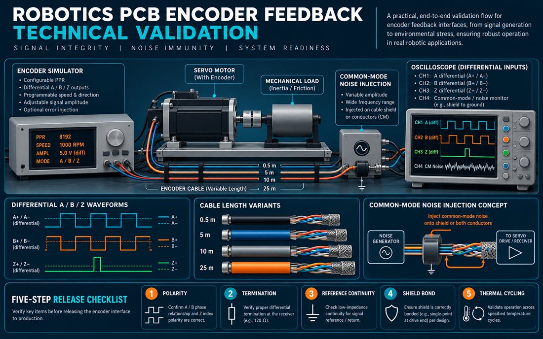
Build a Robotics PCB test matrix before the first pilot: shortest and longest approved cable, shield bonded and intentionally mis-bonded conditions, minimum and maximum supply, encoder speed range, and a representative motor switching pattern. Use an encoder simulator or a known-good motor to separate board behavior from mechanical backlash. Capture A/B/Z at the connector and the receiver pins so the team can see whether the error is introduced by the cable, launch, or board.
Repeat the Robotics PCB matrix after thermal soak. Copper expansion, connector contact resistance, and receiver threshold can move with temperature. Mark the result as a design verification value or engineering range; do not describe it as a customer measurement. During PCB assembly inspection of the Robotics PCB, verify that the connector shell, return vias, and termination parts are soldered without voids or lifted pads.
Release feedback with evidence
A clean Robotics PCB release packet includes the encoder pinout, cable definition, termination option, shield-bond rule, receiver threshold, test fixture connection, and a failure-disposition path. Keep the board revision and firmware decoder revision linked. If a service team changes a cable, the change should trigger a review of the PCB fabrication launch and not only a software regression.
Use a small Robotics PCB pilot build to prove the fixture and the inspection language. PCB prototyping is valuable when the interface includes a new connector, an unusual shield termination, or a dense via transition. Confirm PCB finish compatibility for the connector pads, and document the assembly acceptance method for the receiver and termination parts.
Finally, review the Robotics PCB the signal integrity evidence with the motion team. The best encoder board is not the one with the most copper; it is the one whose phase, return, shield, and test decisions remain explainable when the robot moves from prototype to production.
Sources: encoder and line-receiver manufacturer application notes, Analog Devices guidance on differential interfaces and grounding, Würth and Qorvo references for return paths and EMC, laminate and connector data sheets, and KKPCB capability pages for materials, design, fabrication, assembly, and prototyping. Numbers and limits in this article are design targets or engineering ranges, not customer test results.
