
Table of Contents
A robot controller can pass a functional motion test and still carry a dangerous layout ambiguity. The problem appears where low-voltage logic, safety I/O, motor power, and protective earth meet. A Robotics PCB must make the isolation boundary visible in copper, component placement, coating keep-outs, connector mechanics, and the test record. If the boundary exists only as a line on the schematic, a late routing change can quietly reduce the margin.
This article is for hardware engineers, safety reviewers, and project managers releasing a controller that combines a safe control domain with an actuator or external-power domain. It describes practical geometry and verification decisions without claiming a particular certification, customer test, or measured withstand result.
Treat the isolation boundary as a system boundary
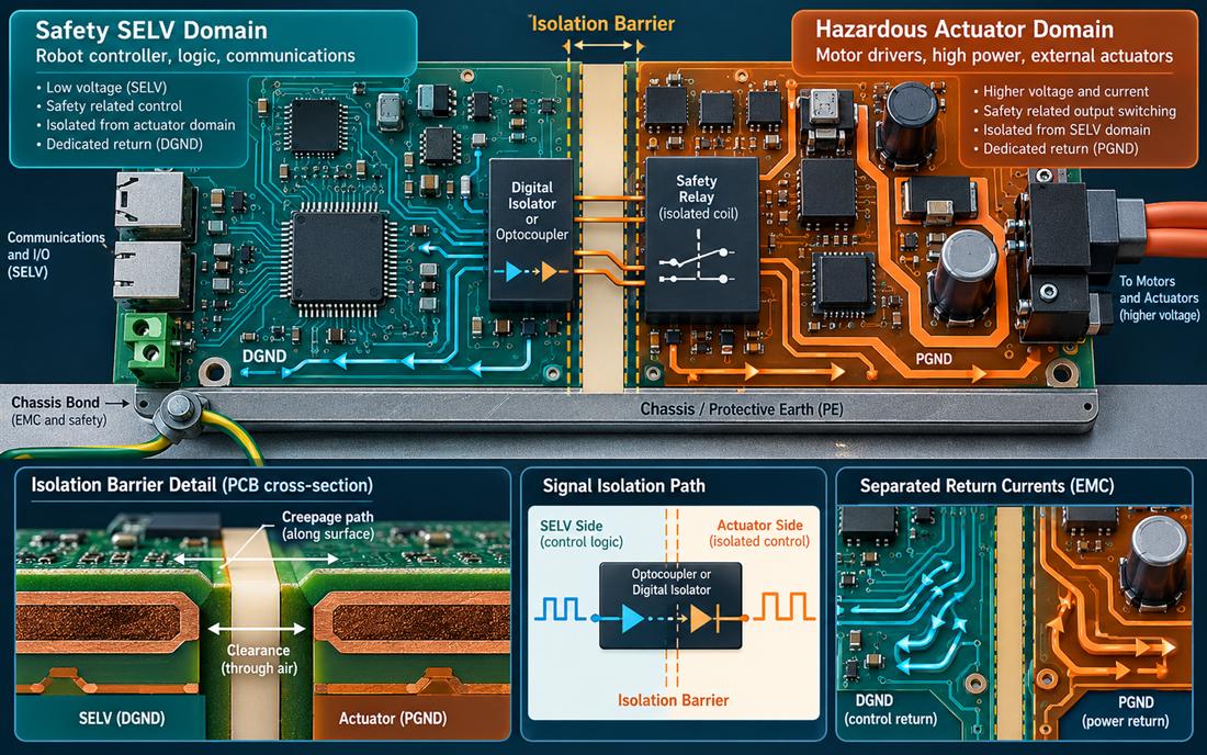
Start with a Robotics PCB domain map. List every signal and energy path that crosses from the SELV or logic side to the actuator side: digital isolator channels, isolated power converters, relay contacts, shield bonds, mounting hardware, and test equipment. The PCB design review should then show the boundary on the stackup, top layer, inner planes, and mechanical drawing.
A practical Robotics PCB boundary is not always a straight slot. It may wrap around an isolated converter, avoid a mounting hole, or separate a connector shield from a logic reference. Mark the keep-out as a controlled feature, assign an owner, and make it part of the release checklist. A “small” copper pour added to improve EMI can be a safety change if it crosses the intended barrier.
Turn creepage into layout geometry
Creepage follows the surface; clearance follows the shortest path through air. Both are affected by slots, solder-mask openings, component bodies, contamination, coating, and the working-voltage and environment assumptions in the product definition. Do not borrow a distance from a previous board without confirming that the same domain, material group, pollution assumption, and installation category apply.
Use slots or cut-outs in the Robotics PCB only when the fabrication drawing can hold their width, edge quality, and registration. Keep copper, vias, pads, silkscreen contamination, and mounting hardware out of the barrier. The released Robotics PCB stackup and PCB materials and surface finish should be named because resin system, mask condition, and residue control affect the actual surface path.
Keep coating and assembly assumptions explicit
Conformal coating can improve environmental robustness, but it must not be used as an unreviewed substitute for spacing. Define coating keep-outs around contacts, slots, test points, and the isolation barrier. A PCB assembly drawing should identify the process, mask openings, inspection points, and the condition under which a coated or uncoated board is accepted.
Keep EMC current out of logic return
Safety and EMC are coupled by current paths. A shield or protective-earth bond should carry its transient current to chassis without forcing that current through the logic return or the isolated-side reference. Place the bond near the enclosure entry, keep the path short and wide, and show the connection in the mechanical and electrical drawings. A high-frequency PCB return-current discipline helps even when the safety signal itself is slow.
Do not create a fence of disconnected copper that looks protective but leaves the current without a low-inductance path. Where stitching vias support the intended return, define pitch, drill, annular ring, and keep-outs. The PCB manufacturing package must preserve those features through panelization, plating, and solder-mask registration.
Verify the fault state
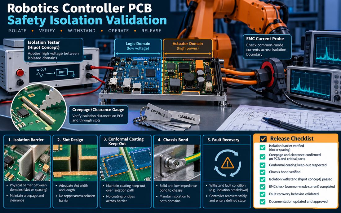
Verification of a Robotics PCB starts with inspection of the physical barrier and continues through electrical tests and fault injection. Check the slot or spacing at the smallest as-built location, confirm that no component lead or solder whisker bridges the boundary, and inspect coating and cleaning residues. For electrical verification, use the approved test method and instrument limits for the product; record the result as a design verification or production acceptance value, not as a generic guarantee.
Exercise realistic faults: loss of the isolated supply, an actuator short, a stuck safety input, a shield-to-chassis change, and a reset during a moving axis. The controller should enter the defined safe state, report the fault, and recover only through the intended sequence. During PCB fabrication review, use coupons or sample pieces to confirm the barrier edge, slot finish, and copper registration before the production lot is released.
Release evidence without overclaiming
A credible Robotics PCB release packet names the assumed voltage domains, spacing rule, material and coating, inspection method, electrical test method, and fault-state acceptance. It also records which items are design targets, which are typical material values, and which are measured on the released lot. Avoid a title such as “certified safety case” unless the certification scope and report are actually available.
Use PCB prototyping to exercise the barrier before tooling and before committing to a dense connector arrangement. Confirm PCB finish compatibility for exposed contacts, document assembly inspection for relay and isolator pins, and include a signal integrity check for fast isolated data channels. The right Robotics PCB evidence lets a sourcing team compare suppliers and maintain a Robotics PCB release record without trading safety geometry for a lower quote.
For final Robotics PCB approval, have the PCB manufacturing and safety owners sign the same drawing revision. If a later motor option, enclosure, or coating changes, reopen the boundary review. A maintainable Robotics PCB controller keeps the isolation decision visible to every team that touches the product.
Sources: applicable safety and insulation design guidance, isolator and power-converter manufacturer application notes, Analog Devices material on isolation and grounding, Würth and Qorvo EMC references, laminate and coating data sheets, and KKPCB capability pages for design, materials, fabrication, assembly, and prototyping. Distances and test descriptions here are engineering review practices, not a certification claim.
