
Table of Contents
A robot controller is rarely repaired on a quiet laboratory bench. A technician works inside a cabinet or joint enclosure, disconnects a harness, replaces a board, and must return the axis to service without creating a new intermittent fault. A Robotics PCB should therefore be designed for connector handling, strain relief, coating, thermal contact, inspection, and serialized replacement—not only for the first power-up.
The Robotics PCB manufacturing risk is cumulative. A Robotics PCB connector that is electrically correct can still fail after cable flexing; a heatsink that meets the drawing can still leave a gap after rework; a coating keep-out that is obvious to the designer can disappear under a fixture. This workflow gives engineering and operations a common release package for a serviceable robotics controller.
Why serviceability belongs in the PCB release
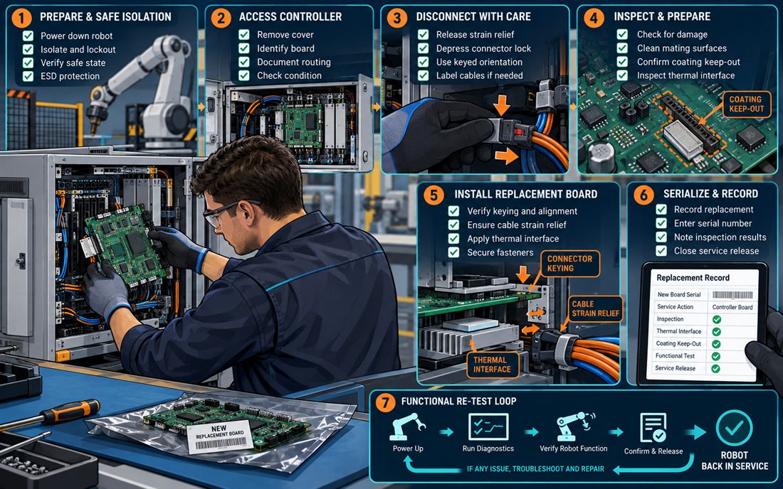
List the service actions for the Robotics PCB before the layout is frozen: safe isolation, cover removal, harness release, board identification, replacement orientation, fastener access, thermal-interface replacement, and functional re-test. Each Robotics PCB service action needs a physical feature on the board or enclosure. The PCB design should show connector keying, accessible test points, mounting datum, and the keep-out around clips and tools.
For a Robotics PCB installed in a moving joint, serviceability also means controlling cable motion. A harness that pulls on a board connector can transfer vibration into solder joints or change the shield bond. Put the strain-relief feature on the mechanical drawing and confirm that the cable bend radius is compatible with the connector and enclosure.
Treat connectors and strain relief as one system
Select the connector for the Robotics PCB for current, signal speed, mating cycles, locking method, and service orientation. Then place the mounting hardware, support posts, and cable clamp before routing the board. The high-current connector and the encoder or vision connector may need different retention and shield strategies. A PCB materials and copper construction review should include pad strength, thermal relief, and any press-fit or screw-terminal requirement.
At assembly, inspect connector coplanarity, solder fillets, pin wetting, and mechanical support. If a connector is hand-soldered during repair, define the allowed process and the inspection point. Use keyed housings or clear orientation marks so a replacement board cannot be installed with a reversed harness. For high-speed signals, keep a controlled-return PCB launch even when the connector is selected mainly for mechanical robustness.

Protect thermal and coating interfaces
A Robotics PCB heatsink or chassis spreader changes the mechanical stack. Define the thermal pad thickness range, fastener torque method, component keep-out, and the inspection evidence that proves contact. Do not let a coating, label, or silkscreen fall into the thermal interface. The PCB manufacturing package should distinguish copper thermal features, exposed pads, mask openings, and any filled or capped vias.
Selective coating should follow the service map. Contacts, test pads, optical components, connector locks, grounding points, and thermal surfaces need explicit keep-outs. A PCB assembly traveler can then tell the operator what is coated, what is masked, and what must be inspected before the board enters the enclosure. If the coating changes, revisit the cable, sensor, and isolation assumptions rather than treating it as a cosmetic process.
Make inspection repeatable
Robotics PCB inspection should be built around the failure modes that matter in the robot: lifted connector pins, cracked solder joints after cable flexing, insufficient thermal contact, damaged coating, blocked test points, and incorrect board orientation. Use visual aids or fixture datums where they reduce interpretation. For a dense controller, combine AOI with a functional fixture that can identify the board revision, firmware, and connector loopback.
Keep a small set of accessible test points for power, reset, communication, safety, and the critical sensor reference. The test point does not need to be large, but it must be reachable after assembly and after coating. Use PCB fabrication coupons or pilot panels to confirm the pad finish, via construction, and board-edge condition before the service procedure is frozen.
Close the maintenance handoff
A Robotics PCB replacement procedure should identify the old board, the new board, the firmware requirement, cable orientation, thermal-interface step, coating condition, and final test. Link the board serial number to the service record so a recurring failure can be grouped by revision or manufacturing lot. A PCB prototyping build is the right place to rehearse the procedure with the actual enclosure and harness.
Before Robotics PCB volume release, verify PCB finish compatibility for connector and test pads, assembly inspection for the rework-sensitive parts, and signal integrity for any fast interface that a service cable touches. Ask the fabricator to review panelization and edge handling, and ask the assembly team to sign the same revision as the service instruction.
A repairable Robotics PCB is not an invitation to loosen engineering controls. It is a board whose connector, thermal, coating, test, and identification decisions remain visible when the product leaves the design office. That visibility is what allows a project manager to reduce mean time to repair without creating a second reliability problem.
Sources: connector and coating manufacturer data sheets, motor-controller and sensor application notes, Analog Devices guidance on mixed-signal service test, Würth and Qorvo references for controlled returns, laminate and finish data, and KKPCB capability pages for design, fabrication, assembly, and prototyping. Process values here are engineering targets and release practices, not customer test results.
