HomeTag

connector launch - KKPCB

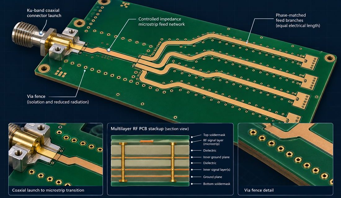
Satellite PCB Ku-Band Feed Networks: Preserving Phase Balance from Launch to Antenna

A Satellite PCB Ku-band feed network is often released as a routing problem, then fails as an integration problem. The electrical design may show equal-length branches and an acceptable nominal impedance, yet the assembled payload can lose phase balance when a connector launch, via fence, housing wall, or harness datum moves the return path. At...
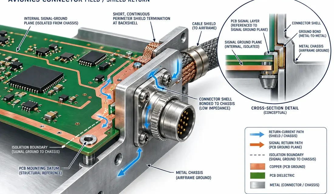
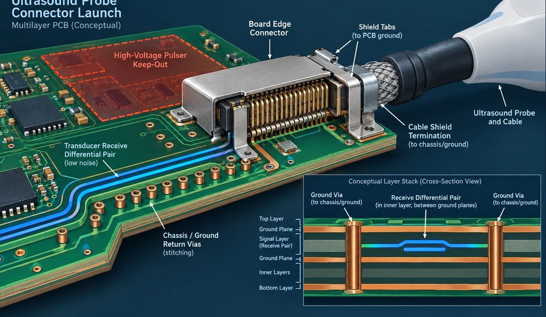
Aerospace PCB Connector Grounding: Where the Board, Backshell, and Chassis Meet

In an aircraft or spacecraft avionics bay, a connector is not merely a mechanical boundary. It is where fast edge currents, cable shields, PCB reference planes, enclosure metal, and installation tolerances meet. A board can pass a schematic review yet radiate or pick up interference after integration because the signal return is forced through a...

Industrial IoT PCB Connector Launch for Long-Cable Networks

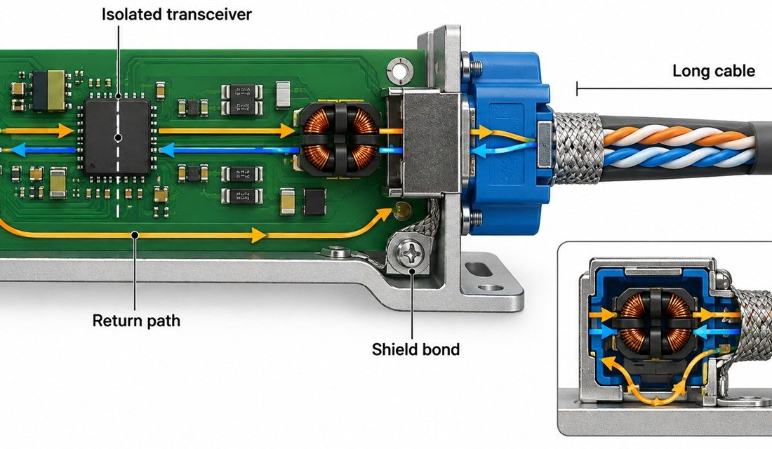
Long RS-485, CAN, or industrial Ethernet cables turn a small controller into a distributed system. The connector, shield, isolation barrier, and return path on an Industrial IoT PCB determine whether a field node communicates reliably after the cable is routed beside motors and contactors. This article focuses on the interface that project teams often postpone:...

Megtron 7 PCB Connector Launches: A Back-Drill and Ground-Return Review for Multi-Gigabit Ports

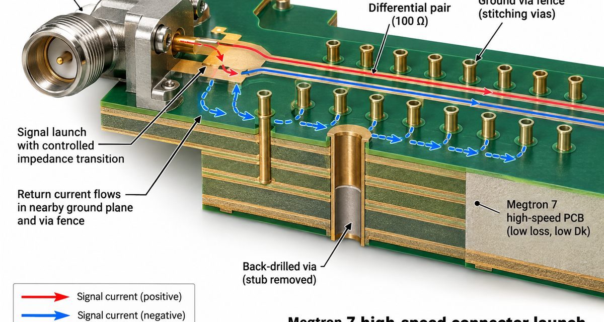
Connector launches often become the hidden bottleneck in a high-speed program. The laminate may have a low loss tangent, but an unused barrel stub, a broken reference plane, or an asymmetric ground-via pattern can dominate the transition. Treat every Megtron 7 PCB as a small RF structure with its own geometry, datum, and verification plan....

Megtron 6 PCB Assembly: A Reflow and Connector-Launch Plan for High-Speed Modules

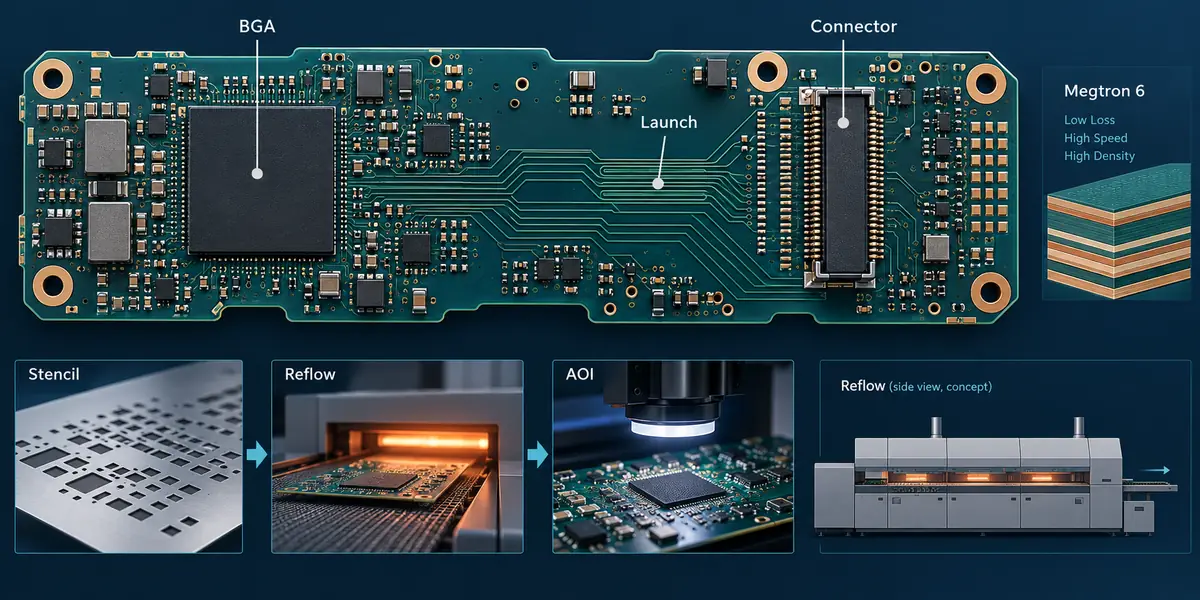
The Megtron 6 PCB connector launch remains the shared datum for SI and assembly inspection. The production Megtron 6 PCB callout should travel with the reflow and inspection package. A connector change on a Megtron 6 PCB is an electrical and assembly change, not only a mechanical edit. For the release team, a Megtron 6...

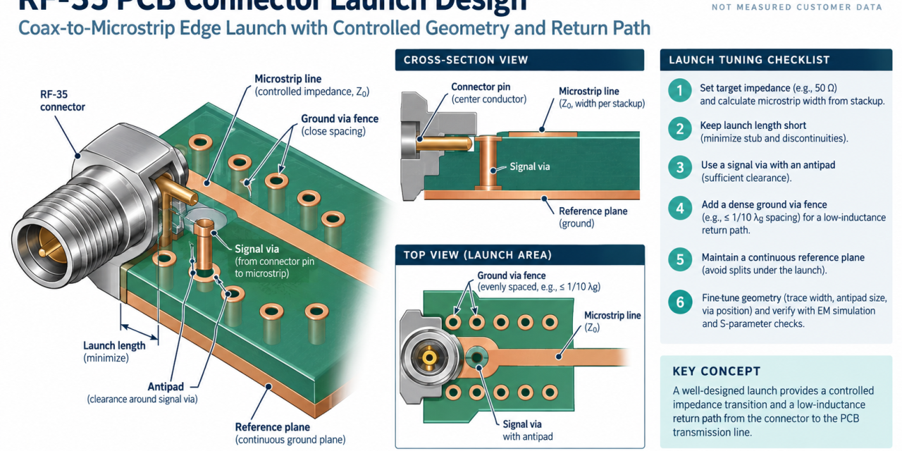
RF-35 PCB Connector Launch and Via Transition: A Practical Verification Workflow

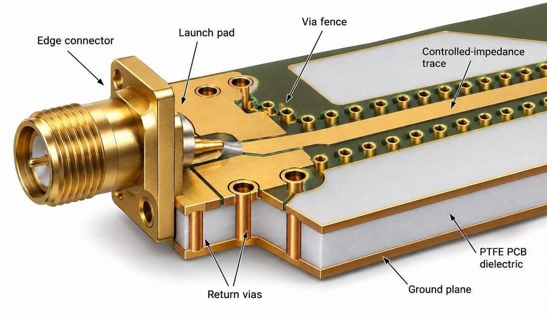
A connector launch is the shortest and most fragile transmission-line section on many microwave boards. The signal leaves a coaxial pin, crosses a pad and via, and then enters a controlled planar line. This guide uses an RF-35 PCB example to show how to release that transition with a defined return path, manufacturable clearances, and...

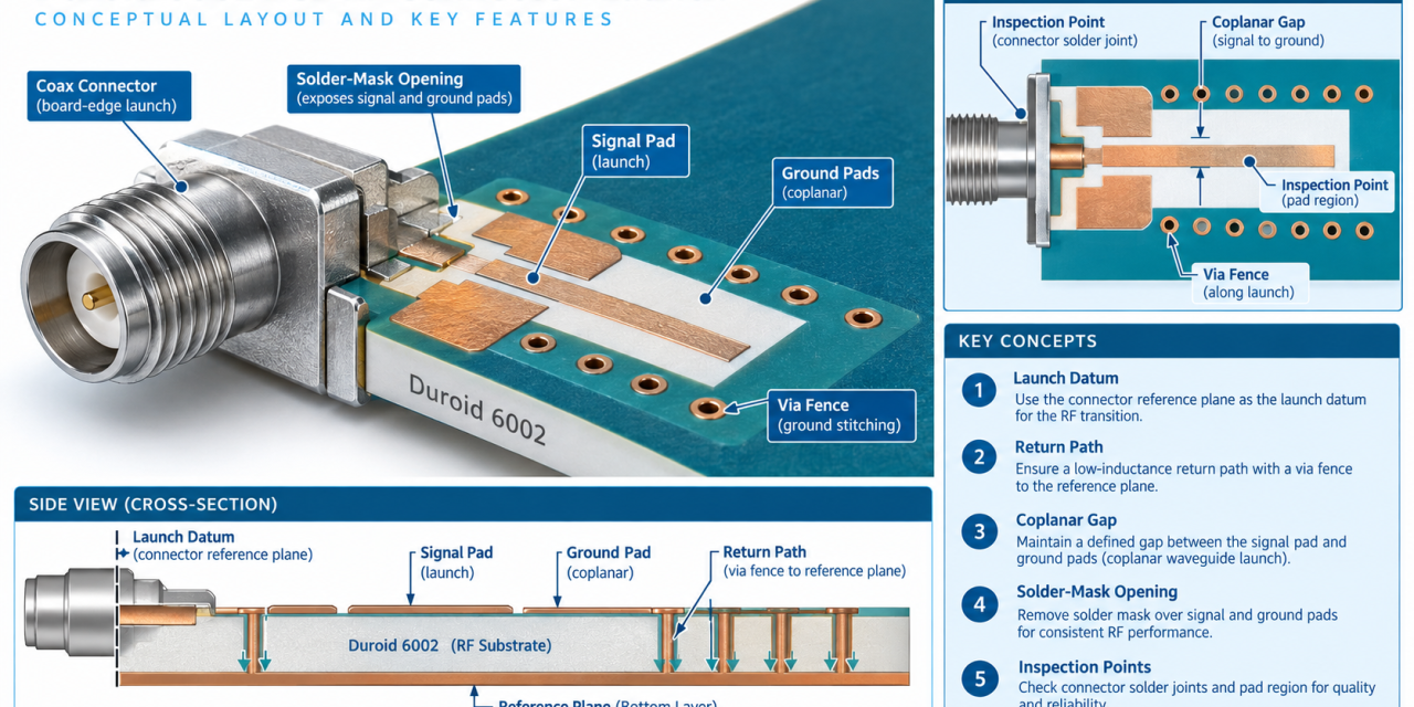
Duroid 6002 PCB Connector Launch: 7 Critical Controls for Reliable RF Assembly

Table of Contents Why connector launches lose margin Seven controls for reliable assembly Launch datum and return path Inspection before release Production handoff checklist When a Duroid 6002 PCB connects a coax, edge connector, or test fixture, the launch is part of the RF circuit—not a mechanical afterthought. Engineers often see good simulated trace performance...

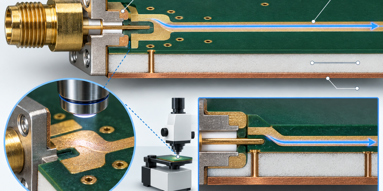
RO5880 PCB Connector Launch: 7 Critical Controls for Reliable RF Assembly

At microwave frequencies, the connector launch is often the first place where a good laminate stackup loses repeatability. The RO5880 PCB release should therefore treat the launch as a controlled subassembly. The finished RO5880 PCB must hold the launch geometry, surface finish, and reference-plane relationship while it moves through panel fabrication and assembly. This guide...