
Long RS-485, CAN, or industrial Ethernet cables turn a small controller into a distributed system. The connector, shield, isolation barrier, and return path on an Industrial IoT PCB determine whether a field node communicates reliably after the cable is routed beside motors and contactors. This article focuses on the interface that project teams often postpone: how the board launches a long cable, defines the shield datum, and proves the transition before volume build.
- Choose the cable, connector, and transceiver as one electrical interface.
- Place common-mode and protection parts where the return path is physically short.
- Separate chassis, isolated, and signal references deliberately.
- Give the test fixture a repeatable cable entry and shield clamp.
Design the connector launch as a current-return problem
The connector footprint is not just a pin map. A PCB design review should show the differential pair or bus, the adjacent reference copper, the shield shell, and the first return-via or chassis connection. If the pair leaves the connector over a split or a void, the current must find a longer path before the transceiver. The Industrial IoT PCB stackup should therefore be defined before the connector escape is frozen.
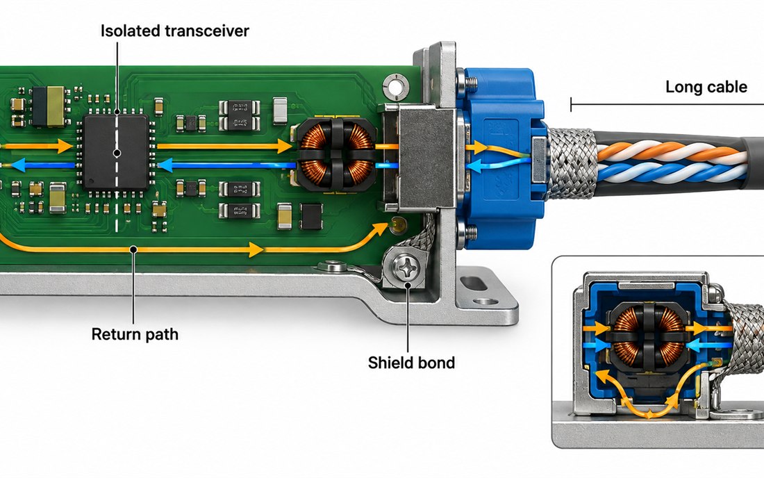
Place the common-mode choke, transient clamp, and termination according to the intended signal path, not according to the empty space left after routing. The high-frequency PCB rules may control pair geometry, but the connector shell and chassis bond still need a mechanical datum. Record torque, washer, and shield-clamp assumptions in the PCB manufacturing package.
Keep isolation and reference planes explicit
An isolated transceiver can separate logic ground from the field side, but the board still needs a clear location for cable shield energy and surge current. Use a named barrier, controlled crossing, or capacitive return only when the system architecture supports it. Avoid a “floating” shield note that each factory interprets differently. The PCB assembly drawing should identify the part orientation, isolation slot, and shield hardware installation order.
| Interface item | Common mistake | Release evidence |
|---|---|---|
| Connector shell | Shell floats or bonds at an unintended point | Mechanical datum and shield note |
| Pair reference | Pair crosses a split or loses return vias | Layer overlay and impedance note |
| Protection | Clamp is electrically far from the entry | Placement review and assembly photo |
| Isolation | Probe or hardware bridges the barrier | Fixture drawing and inspection point |
The PCB materials choice affects dielectric spacing, loss, and assembly temperature, but it does not replace a complete launch review. Keep a substitute material list tied to the same stackup revision so a purchasing change does not quietly move the pair or the shield return.
Build the cable test around a repeatable fixture datum
Bench leads are often short, unshielded, and routed in free air. A production fixture should use the intended cable family, connector torque, clamp position, and enclosure datum. The assembly fixture should also protect the isolated transceiver from accidental probe contact. A conceptual setup is shown below; it explains the workflow and does not claim a measured customer result.
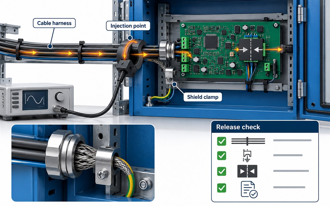
Define which observation is a design target, which is a production acceptance check, and which is a system-level qualification. The PCB fabrication traveler should preserve board revision, cable revision, fixture revision, and acceptance method. If an operator changes the cable length, the record should show that change rather than hiding it inside a generic “noise test” step.
What changes require a fresh connector review?
- Changing the transceiver package or isolation component.
- Moving the connector, shield clamp, or enclosure mounting hardware.
- Changing the cable family, braid termination, or connector torque.
- Changing the stackup, reference-plane thickness, or via-fence pattern.
- Changing the coating, cleaning process, or approved material substitute.
A robust Industrial IoT PCB release makes the field interface inspectable. The return-path review, the fabrication release, and the assembly traveler should point to the same connector datum. That gives engineering and production a common answer when an installed cable behaves differently from a bench lead.
The project manager should receive a single handoff containing the connector drawing, stackup, cable specification, fixture photograph, and change log. Procurement can then approve the approved laminate and signal-integrity rule without separating them from the mechanical interface.
The Industrial IoT PCB stackup should stay beside the cable drawing, and the Industrial IoT PCB layout should preserve the connector datum after an ECO.
Freeze the connector interface at pilot release
For an Industrial IoT PCB, the Industrial IoT PCB connector datum, cable family, and shield bond belong in the same release package. If an Industrial IoT PCB changes its isolated transceiver, repeat the return-path review. If an Industrial IoT PCB changes its enclosure, repeat the cable-entry check. The Industrial IoT PCB fixture should preserve the same clamp and probe position. A production Industrial IoT PCB record should distinguish a design target from a measured result.
The Industrial IoT PCB traveler should retain cable length and shield-clamp identity, while the Industrial IoT PCB inspection photo should show the connector datum after assembly.
The Industrial IoT PCB release owner should sign the connector, stackup, and fixture assumptions together. That is the point at which an Industrial IoT PCB becomes repeatable manufacturing data rather than a bench-only experiment.
Industrial IoT PCB handoff notes
The Industrial IoT PCB handoff names the cable, connector, shield, and isolated transceiver. A later Industrial IoT PCB revision must carry the same datum through fabrication. The Industrial IoT PCB assembly traveler should show the shield clamp. The Industrial IoT PCB test fixture should show the injection point. The Industrial IoT PCB change log should state whether a value is a target or a measured production observation.
Use a short pilot checklist for every Industrial IoT PCB: connector torque, cable family, shield bond, fixture datum, board revision, and acceptance method. Keeping these six items on the traveler helps engineering, production, and procurement discuss the same interface.
Sources: Analog Devices interface and isolation guidance; Würth Elektronik EMC, grounding, and connector notes; Qorvo RF integration references; industrial transceiver, cable, connector, and PCB material supplier application data. The checks above are engineering release practices, not customer qualification results.
