HomeTag

radar PCB - KKPCB

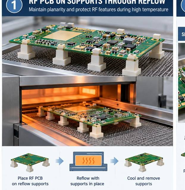
What the Assembly Line Can Change on a Radar PCB

Radar PCB assembly release begins by treating heat, solder, cleaning, and mechanical force as RF variables. An RF board can leave fabrication within drawing limits and still change during paste printing, reflow, shielding, cleaning, or mechanical assembly. That risk is amplified in short-range and imaging radar front ends where antenna phase error, launch repeatability, and...

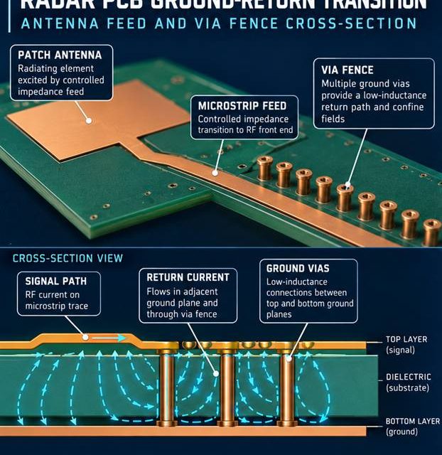
A Ground-Return Strategy for Radar PCB Antenna Transitions

Radar PCB launch design begins with a complete three-dimensional signal and return path. The boundary between a board and a connector, coax, antenna, or shield is where a clean schematic becomes a three-dimensional electromagnetic problem. In short-range and imaging radar front ends where antenna phase error, launch repeatability, and thermal drift all affect detection margin,...

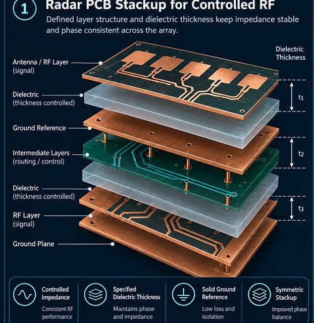
How a Radar PCB Stackup Preserves Phase Consistency Across the Array

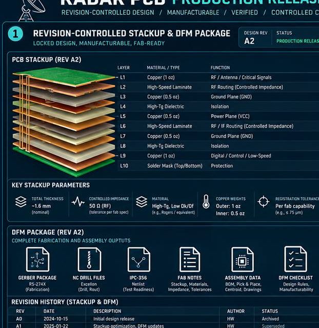
Radar PCB stackup release begins by making every electromagnetic and manufacturing assumption visible. Stackup discussions fail when the drawing lists layer names but not the electromagnetic and manufacturing assumptions behind them. In short-range and imaging radar front ends where antenna phase error, launch repeatability, and thermal drift all affect detection margin, the board must carry...

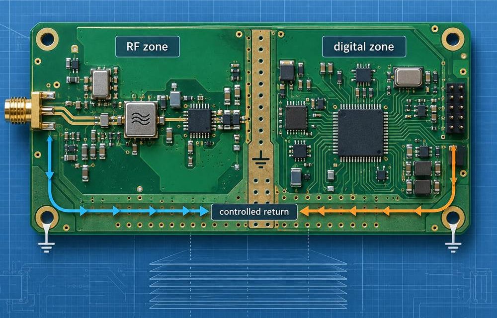
Taconic TLY-5 PCB Mixed-Signal Layout: A Return-Path Plan for GNSS and Radar

Table of Contents Separate RF, clock, power, and digital return paths Select layer transitions that preserve reference continuity Protect GNSS and radar interfaces during assembly Release a mixed-signal verification plan GNSS receivers and compact radar modules bring incompatible noise budgets onto the same board. The RF path needs a quiet reference and controlled geometry; the...

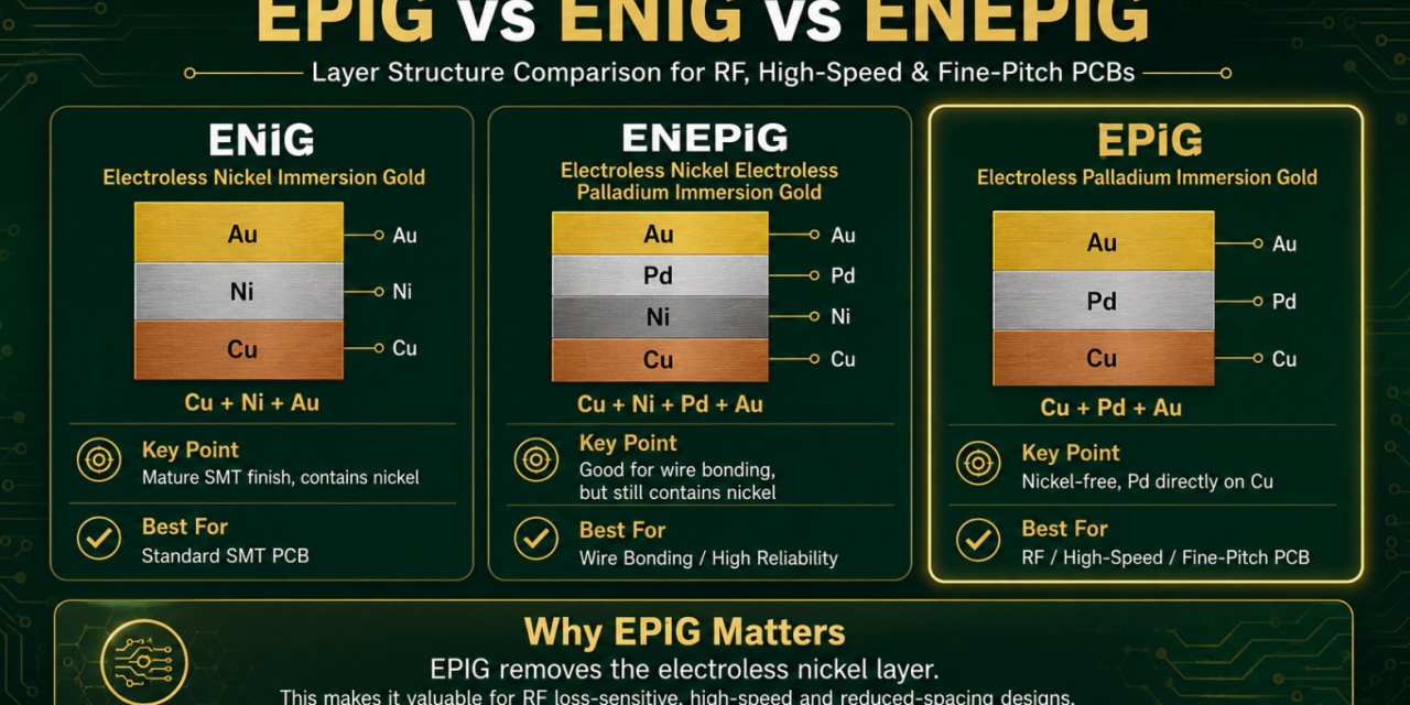
EPIG vs ENIG vs ENEPIG for RF, microwave, high-speed and fine-pitch PCB designs

For standard SMT PCBs, surface finish is often selected for solderability, storage life and cost. But for RF, microwave, high-speed PCB, HDI, fine-pitch, radar, satellite communication, 5G RF and defense communication PCBs, surface finish can become part of the electrical performance discussion. The key question is not simply: Which gold finish is better? The better...

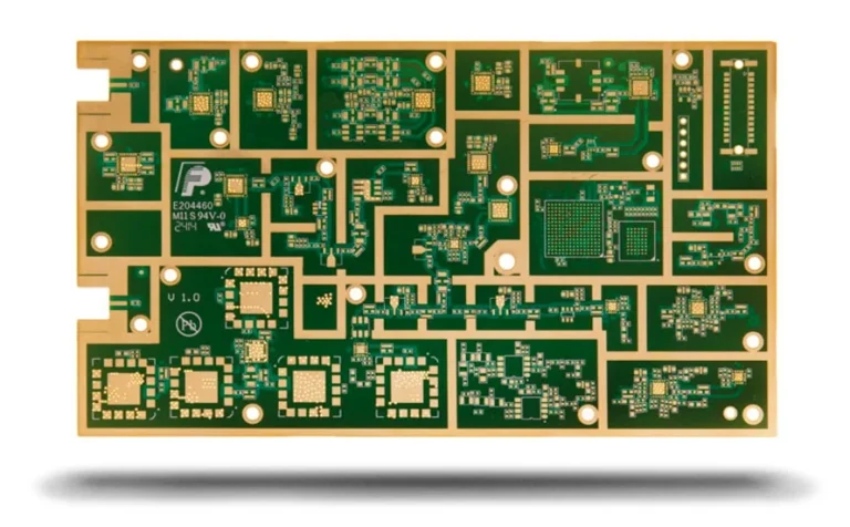
Low Dissipation Factor PCB: Ultra-Low-Loss PCB Solutions for High-Speed and RF Applications

Why Low Dissipation Factor PCB Technology Is Essential Modern electronic systems are rapidly evolving toward: Higher operating frequencies Faster data transmission Multi-gigabit networking Advanced RF communication High-density electronic integration Applications such as: 5G communication infrastructure AI servers and data centers Radar systems Satellite communication equipment High-performance networking platforms require PCB materials capable of delivering: Extremely...

Duroid 6010 PCB: High-Dielectric RF PCB Solutions for Microwave, Radar, and Aerospace Applications

Why Duroid 6010 PCB Technology Is Important Modern RF and microwave systems are rapidly evolving toward: Higher operating frequencies Compact antenna integration Advanced radar systems High-density RF modules Miniaturized microwave electronics Applications such as: Aerospace communication systems Automotive radar platforms Satellite communication equipment Military RF electronics Microwave sensing systems require PCB materials capable of delivering:...

TLY-5 PCB: Ultra-Low-Loss RF PCB Solutions for Microwave, 5G, and Radar Applications

Why TLY-5 PCB Technology Is Important Modern wireless communication systems are rapidly advancing toward: Higher operating frequencies Faster wireless transmission Greater communication bandwidth Compact RF module integration Ultra-low-loss microwave performance Applications such as: 5G and mmWave communication Automotive radar systems Satellite communication equipment Aerospace RF electronics Microwave networking infrastructure require PCB materials capable of delivering:...