HomeTag

RF Stackup - KKPCB

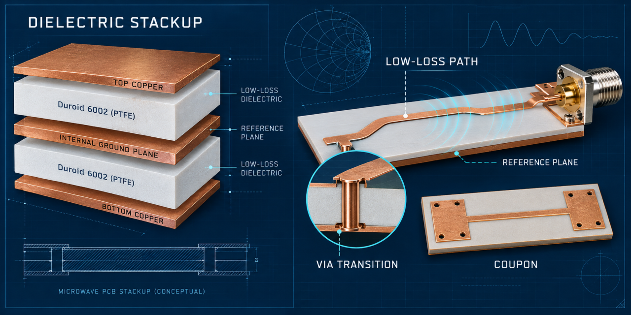
Duroid 6002 PCB Low-Loss Stackup: 7 Critical Controls for Microwave Module Stability

Contents Why low-loss stackup choices drift Seven controls for a stable release Fabrication and inspection flow Project checklist Duroid 6002 PCB projects are often selected for low-loss microwave behavior, then challenged by stackup substitutions, via transitions, and panel process changes. The project pain point is usually not the material name. It is the gap between...
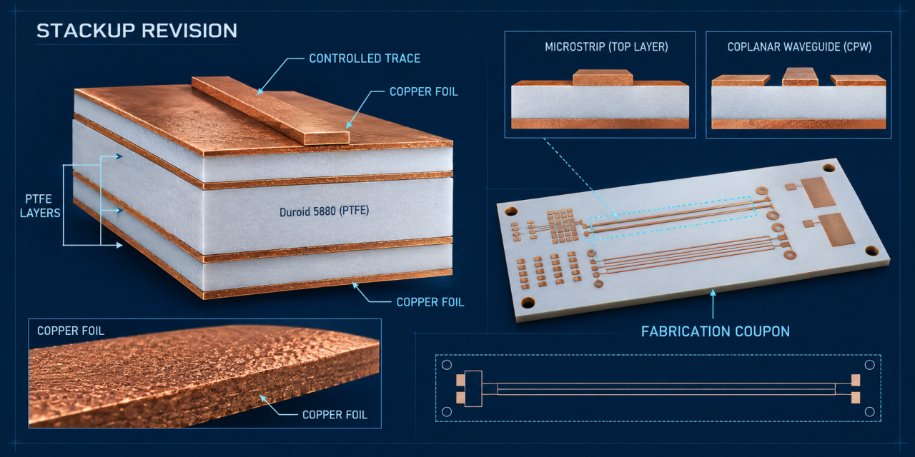
Duroid 5880 PCB Stackup: 6 Critical Controls for Stable Impedance Release

Contents Why stackup drift changes RF behavior Six stackup and impedance controls Coupon and release workflow Release checklist Duroid 5880 PCB stackup decisions determine whether an RF design can move from field model to repeatable fabrication. A nominal dielectric value is not enough. Pressed thickness, copper foil, roughness, trace geometry, and coupon correlation all influence...

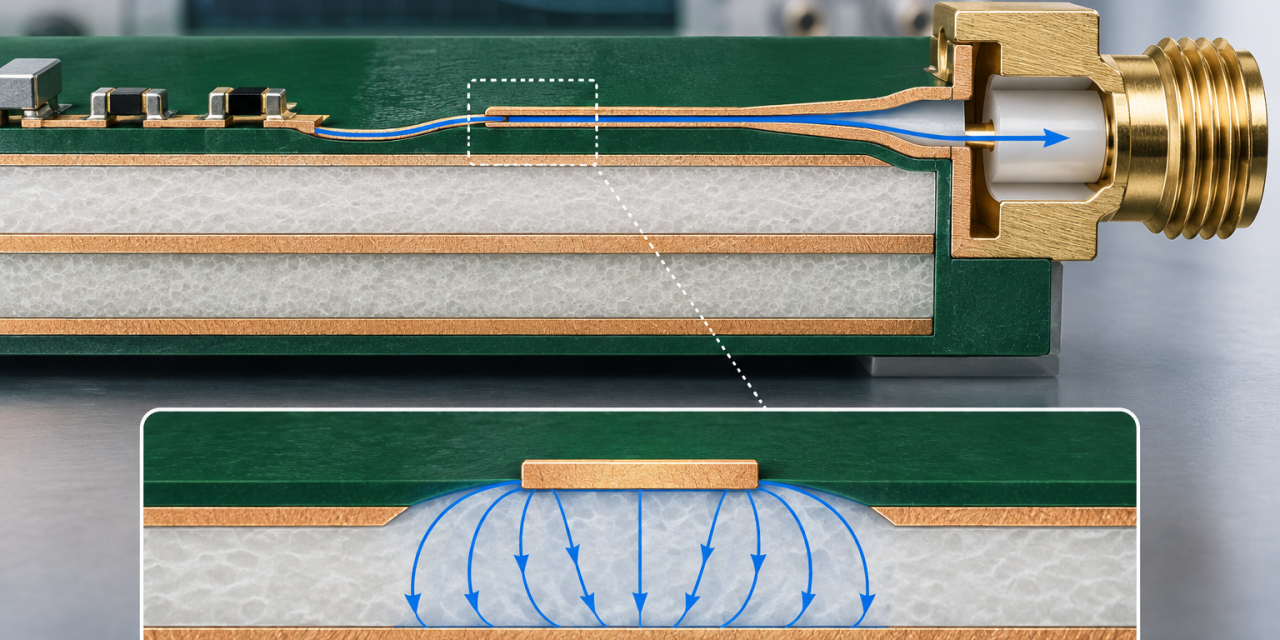
Duroid 5880 PCB Stackup: 7 Critical Controls for Low-Loss RF Fabrication

Microwave design teams often choose Duroid 5880 for its low-loss behavior, then discover that stackup translation and fabrication details decide whether the finished board matches the model. A production-ready Duroid 5880 PCB needs a controlled dielectric reference, consistent copper geometry, and inspection points that survive panel processing. This guide turns those requirements into a practical...

RO4003C PCB Stackup Release: Managing Dielectric Thickness in Compact RF Modules

Compact RF modules often fail between schematic approval and fabrication release because the RO4003C PCB stackup is treated as a static drawing. Resin content, copper thickness, press-out, and reference-plane choices change the field geometry that the RF model used. A controlled RO4003C PCB stackup release turns those assumptions into a buildable document for engineering and...

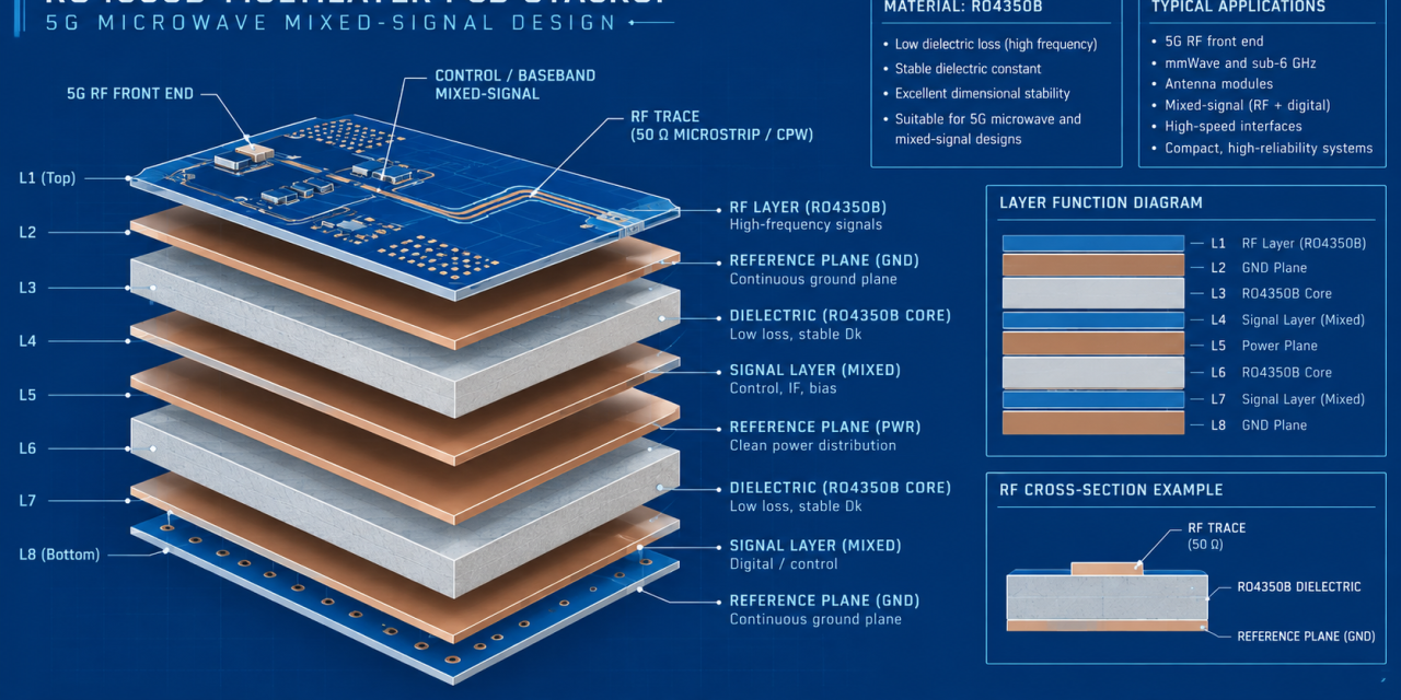
RO4350B PCB Stackup Selection for 5G and Microwave Mixed-Signal Boards

When a radio board combines a 5G front end, clock distribution, and digital processing, stackup selection becomes a system decision rather than a material shortcut. An RO4350B PCB can provide a predictable RF foundation, but only when the chosen dielectric thickness, copper, reference planes, and mixed-signal boundary are carried consistently into fabrication. This guide gives...

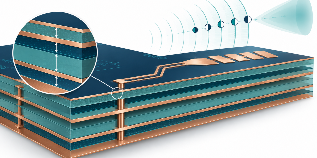
RO4835 PCB Stackup Decisions for 77 GHz Radar Phase Stability

At millimeter-wave frequencies, a small dielectric or registration change can move the phase of an antenna feed enough to reduce array margin. The practical question is not simply whether an RO4835 PCB is low loss; it is how the stackup, copper geometry, and fabrication handoff keep phase repeatable from prototype to production. This engineering guide...

Engineering Duroid 6010 PCB for Extreme High-Frequency, Low-Loss, and Ultra-Stable Microwave Applications

As microwave, satellite, radar, and millimeter-wave systems move deeper into high GHz operating regions, engineers require PCB materials with ultra-stable dielectric behavior, extremely high Dk, and exceptionally low loss. This is where Duroid 6010 PCB—based on Rogers RT/duroid® 6010LM—becomes a foundational choice for critical RF and microwave engineering. With a dielectric constant (Dk) of ~10.2,...

Engineering Double Layer HF PCB for Ultra-Stable RF Performance and Low-Loss Microwave Signal Integrity

As RF communication, IoT edge devices, automotive radar, and compact wireless modules continue to evolve, the Double Layer HF PCB has become a preferred architecture for delivering high-frequency stability, low insertion loss, and predictable electromagnetic performance. Although limited to two copper layers, a Double Layer HF PCB—when engineered correctly—can outperform many multilayer structures in signal...