HomeCategory

PCB Materials | FR-4, High-Frequency, Low-Loss & Heavy Copper - KKPCB

IoT IC Test PCBs: Enabling Reliable Testing for Connected Devices

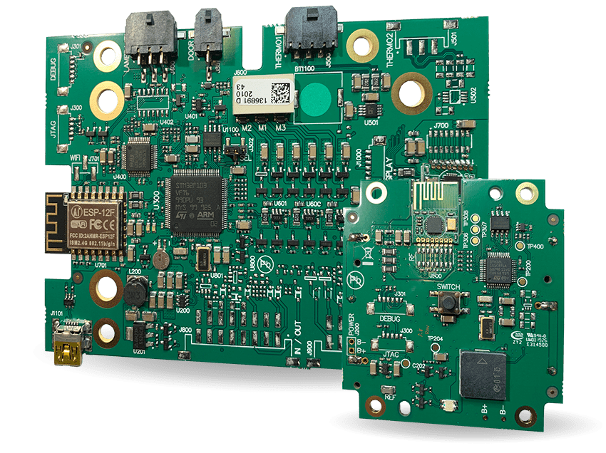
IoT Testing Challenges Testing IoT integrated circuits introduces a unique combination of challenges. Unlike purely digital or RF chips, IoT devices integrate: Wireless communication (Wi-Fi, BLE, LoRa, NB-IoT) Low-power operation modes Mixed-signal functionality (analog + digital + RF) An IoT IC Test PCB must support all these domains simultaneously while maintaining accuracy, repeatability, and efficiency....

RF IC Test PCBs: Precision Platforms for High-Frequency Device Validation

Why RF IC Testing Is Fundamentally Different Testing RF integrated circuits is significantly more demanding than standard digital testing. An RF IC Test PCB must handle GHz-level signals, where even small discontinuities can distort measurement results. Unlike digital systems, RF testing is highly sensitive to: Signal loss and phase shift Impedance discontinuities Parasitic effects from...

Custom ATE PCBs: From Specification to Production-Ready Test Platforms

What Makes an ATE PCB Truly “Custom”? A Custom ATE PCB is not just a modified test board—it is a fully tailored interface designed around a specific combination of: Device Under Test (DUT) Test socket and mechanical interface ATE system architecture Signal, power, and timing requirements Unlike standard PCBs, every aspect—from pin mapping to stack-up—is...

HDI PCBs Explained: Stack-Up Choices, Via Strategies, and Cost Trade-Offs

What Actually Defines an HDI PCB? An HDI PCB (High-Density Interconnect PCB) is not defined by layer count alone, but by how efficiently interconnections are implemented. The key differentiators are: Microvias (laser-drilled vias) Blind and buried vias Fine line and spacing (typically ≤100 µm) High connection density per unit area The goal of HDI is...

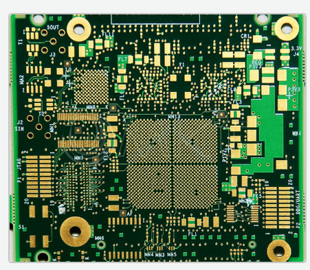
High Pin Count PCBs: Managing Complexity in Advanced Electronic Systems

System Complexity as the Driving Force Modern electronic systems are no longer defined by individual components, but by highly integrated devices with massive I/O requirements. CPUs, GPUs, FPGAs, and advanced SoCs now feature hundreds to thousands of pins, driving the need for High Pin Count PCBs. This shift introduces a new level of complexity: Multiple...

Low Loss PCBs: Minimizing Signal Attenuation in High-Speed and RF Designs

Why Loss Matters in Modern PCB Design As data rates and frequencies continue to increase, signal loss becomes one of the primary limiting factors in PCB performance. In high-speed digital systems and RF designs, excessive loss leads to: Signal degradation and eye diagram closure Reduced transmission distance Increased bit error rates (BER) Lower system reliability...

Custom ATE PCBs: Tailored Solutions for Precision Semiconductor Testing

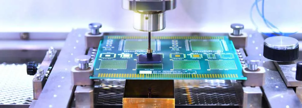
Why Custom ATE PCBs Matter In semiconductor testing, off-the-shelf solutions rarely meet the requirements of modern devices. A Custom ATE PCB is specifically engineered to match the electrical, mechanical, and performance requirements of a particular device under test (DUT) and its associated test platform. Unlike general-purpose test boards, custom ATE PCBs are designed to: Match...

Multilayer Test PCBs: Reliable Platforms for High-Performance Electronic Testing

Role in Test Systems A Multilayer Test PCB is a specialized board used in electronic testing environments, particularly in systems involving Automated Test Equipment (ATE), validation platforms, and high-speed signal verification. Unlike standard PCBs, test boards are not part of the final product—they serve as temporary but critical platforms that ensure devices function correctly before...

5G mmWave PCBs: Engineering for Ultra-High Frequency Performance

Why mmWave Changes Everything The transition from sub-6 GHz to millimeter wave (mmWave) frequencies fundamentally changes PCB design. Operating typically between 24 GHz and 100 GHz+, mmWave systems push PCB technology to its limits. At these frequencies, the PCB is no longer just a passive interconnect—it becomes an active part of the RF system, directly...

Duroid 6002 PCBs: Stable Dielectric Performance for Precision RF Designs

Why Duroid 6002? In RF and microwave PCB design, consistency is often more critical than absolute performance. Duroid 6002 PCB, based on Rogers RT/duroid 6002 laminate, is widely chosen for its exceptionally stable dielectric constant and predictable electrical behavior. With a dielectric constant (Dk) of approximately 2.94 and a low dissipation factor, this material offers...