HomeAuthor

kkpcb02 - KKPCB - Page 6 of 15

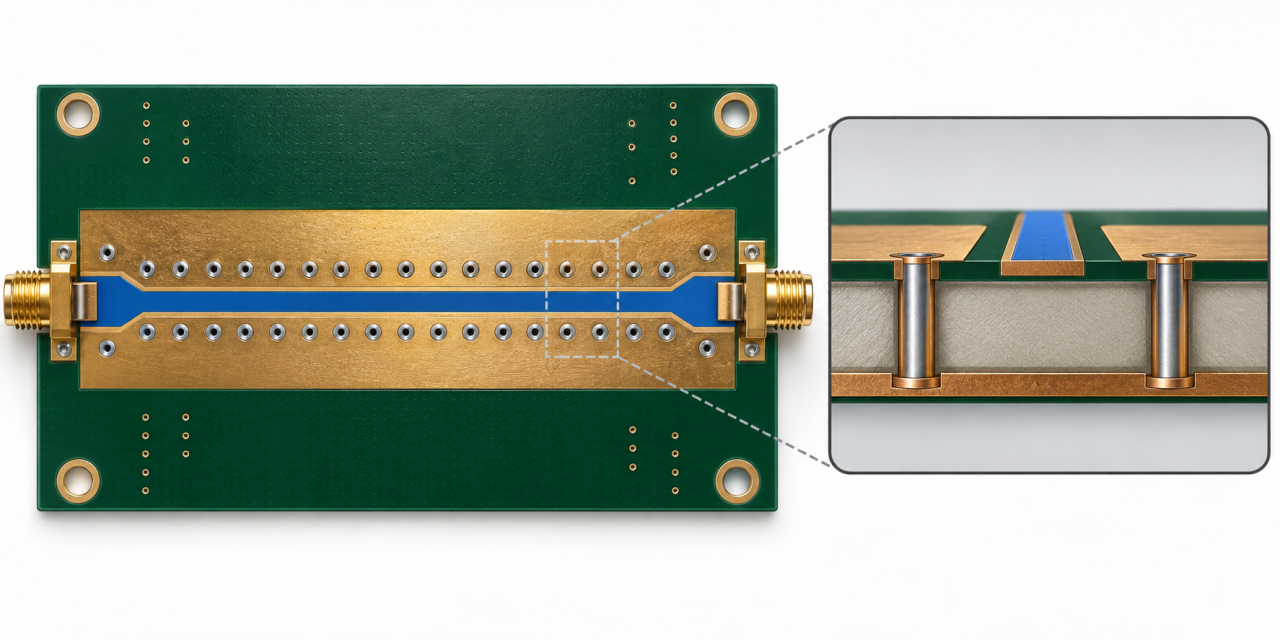
Duroid 5880 PCB Stackup: 6 Critical Controls for Stable Impedance Release

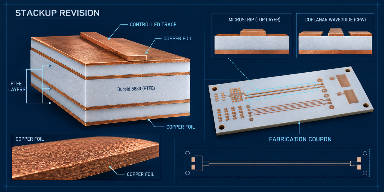
Contents Why stackup drift changes RF behavior Six stackup and impedance controls Coupon and release workflow Release checklist Duroid 5880 PCB stackup decisions determine whether an RF design can move from field model to repeatable fabrication. A nominal dielectric value is not enough. Pressed thickness, copper foil, roughness, trace geometry, and coupon correlation all influence...
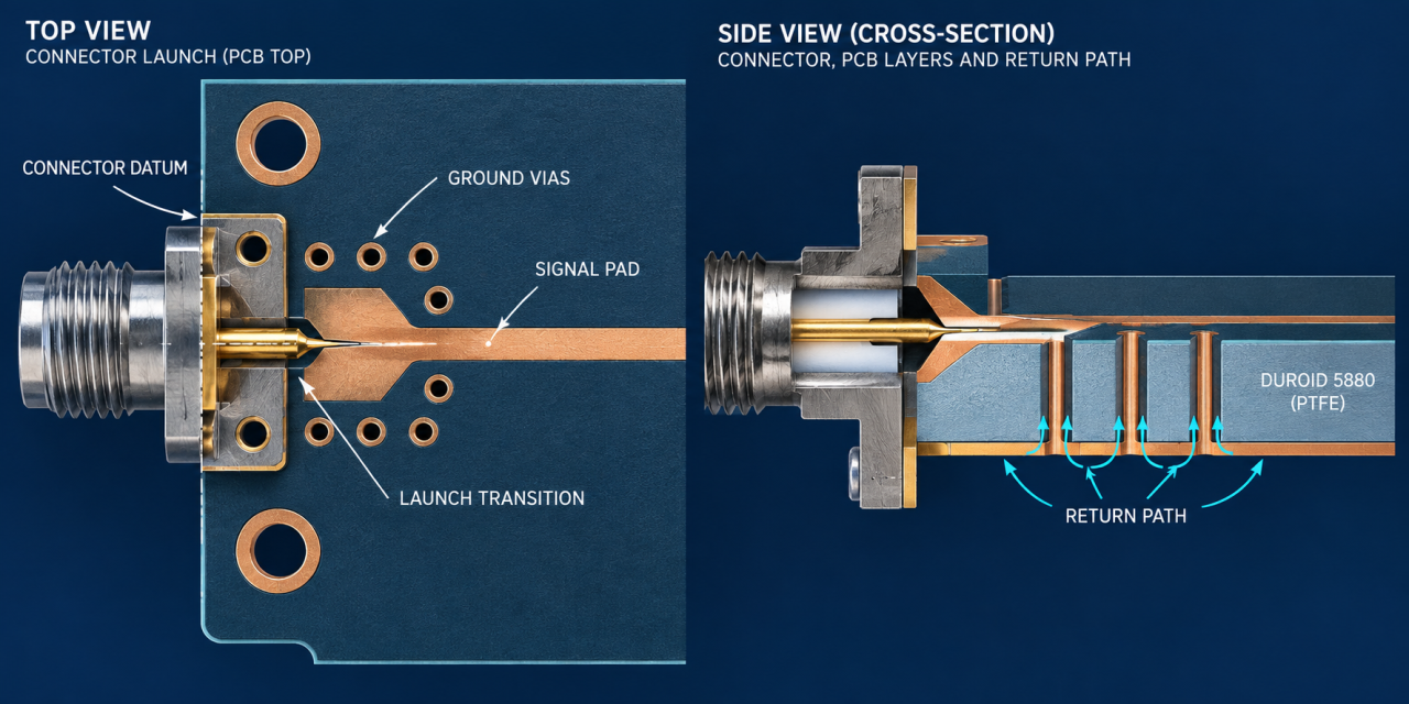
Duroid 5880 PCB Connector Launch: 8 Critical Controls for Repeatable RF Assembly

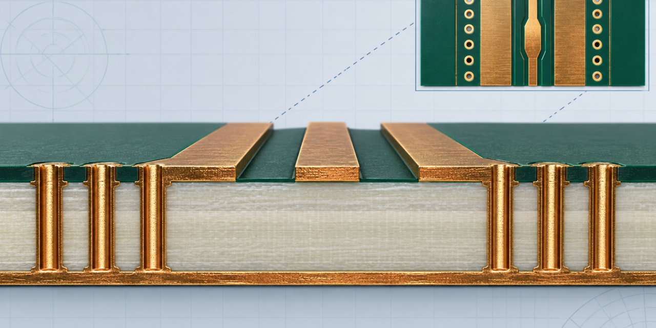
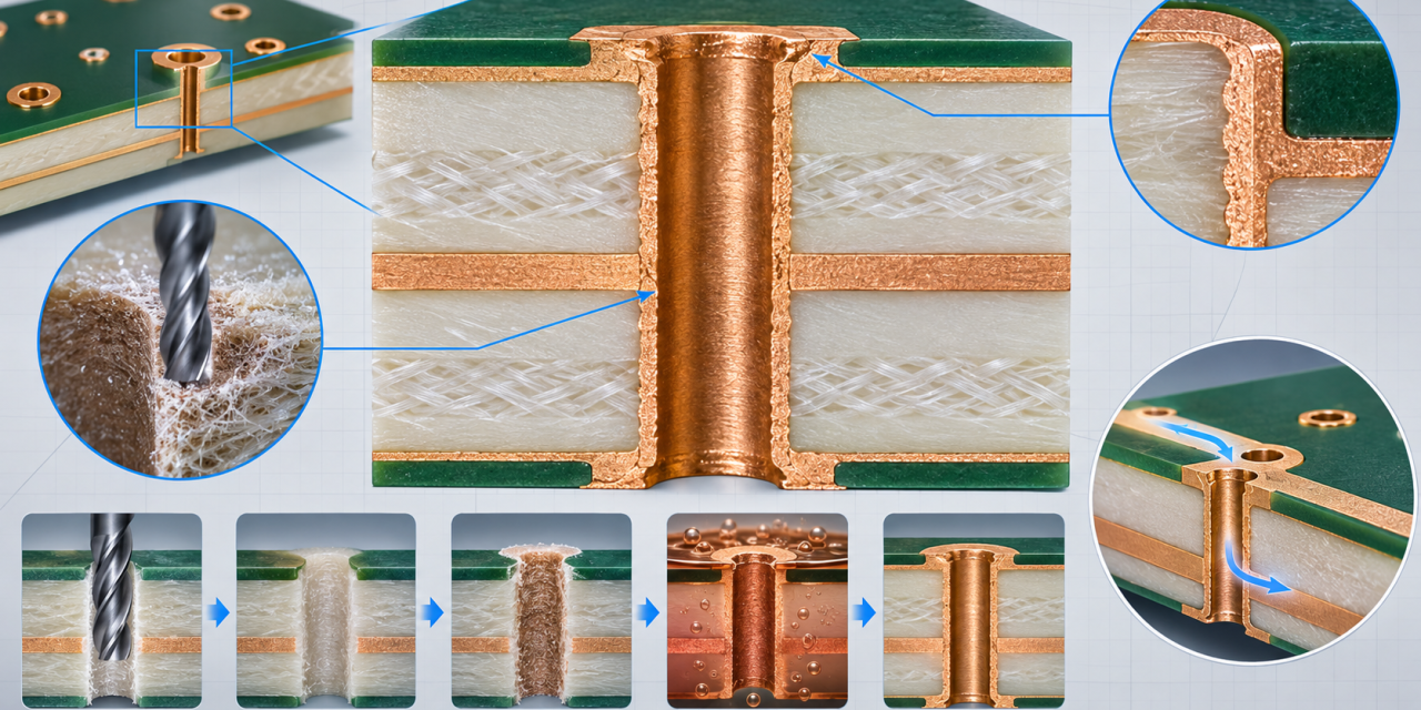
Contents Why the connector launch controls RF yield Layout and datum controls Assembly and inspection controls Release checklist Duroid 5880 PCB connector launches are a common project pain point. A layout can meet the simulated impedance target and still show return-loss variation when the connector datum, plated holes, solder fillet, or ground-via pattern changes during...

Duroid 5880 PCB Dimensional Stability: 7 Critical Controls

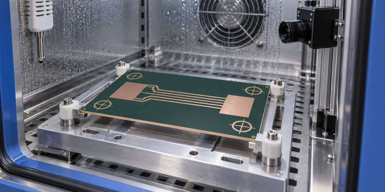
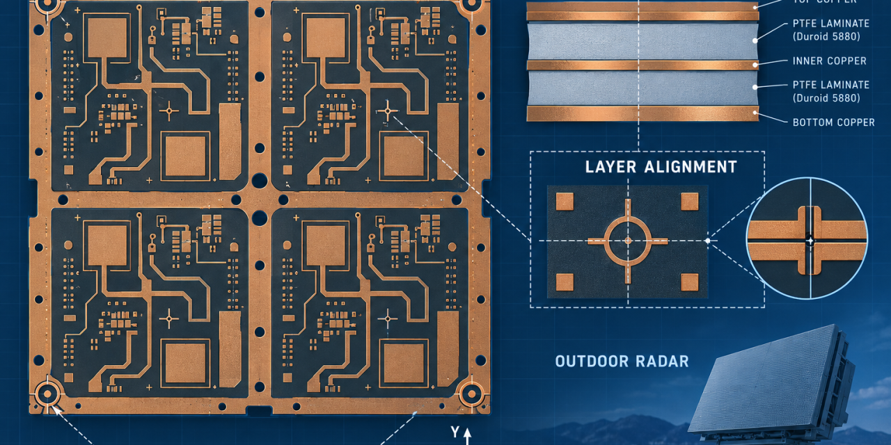
Contents Why dimensional stability becomes an RF problem Seven production controls Outdoor radar release checklist Key takeaway Duroid 5880 PCB projects for outdoor radar often fail at the mechanical-to-RF interface rather than in the laminate specification. Seasonal temperature, moisture conditioning, panel handling, and connector datum changes can move a launch or array cell enough to...

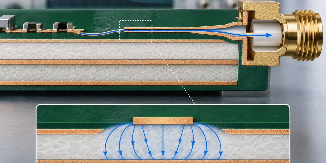
Duroid 5880 PCB Stackup: 7 Critical Controls for Low-Loss RF Fabrication

Microwave design teams often choose Duroid 5880 for its low-loss behavior, then discover that stackup translation and fabrication details decide whether the finished board matches the model. A production-ready Duroid 5880 PCB needs a controlled dielectric reference, consistent copper geometry, and inspection points that survive panel processing. This guide turns those requirements into a practical...

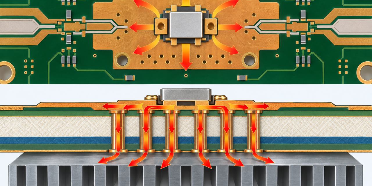
RO5880 PCB Thermal Design: 6 Critical Controls for High-Power RF Modules

High-power microwave modules often fail at the thermal interface before they fail in the RF model. The finished RO5880 PCB must move heat away from the active device without disturbing the reference plane, launch geometry, or assembly datum. This engineering guide explains how to turn copper spreading and thermal-via decisions into a controlled design release...

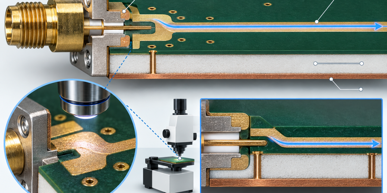
RO5880 PCB Connector Launch: 7 Critical Controls for Reliable RF Assembly

At microwave frequencies, the connector launch is often the first place where a good laminate stackup loses repeatability. The RO5880 PCB release should therefore treat the launch as a controlled subassembly. The finished RO5880 PCB must hold the launch geometry, surface finish, and reference-plane relationship while it moves through panel fabrication and assembly. This guide...

RO5880 PCB Dimensional Stability: Managing Moisture and Registration in Outdoor Radar

Outdoor radar and microwave equipment can see humidity, temperature swings, and repeated handling before a board reaches final system test. For a PTFE-based laminate, the project risk is not only RF loss; it is whether the finished RO5880 PCB keeps its layer registration, connector datum, and antenna geometry through the approved process. This RO5880 PCB...