HomeTag

Radar Antenna PCB - KKPCB

Keeping Radar Geometry Stable Through Automotive Radar Sensor PCB Assembly

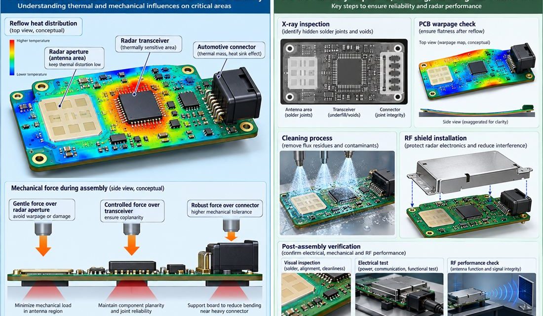
Automotive Radar Sensor PCB — Fabrication can meet a drawing and assembly can still move the electrical result. Paste height, reflow warpage, shield force, cleaning chemistry, heat spreaders, and connector rework all act on front, corner, and short-range radar sensor boards using a 76–81 GHz antenna aperture, transceiver, processor, and sealed housing. This production guide...

Controlling the 76–81 GHz Launch on an Automotive Radar Sensor PCB

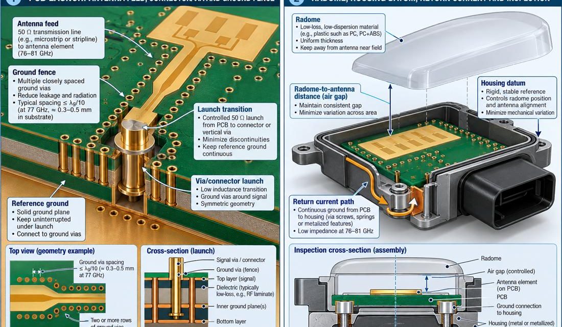
Automotive Radar Sensor PCB — The connector, coax, antenna, sensor flex, or board edge is where a schematic becomes a three-dimensional part. In front, corner, and short-range radar sensor boards using a 76–81 GHz antenna aperture, transceiver, processor, and sealed housing, that interface also has to survive mating force, housing tolerances, and service handling. This...

Radar PCB Design: Materials, High-Frequency Layout Techniques & Applications

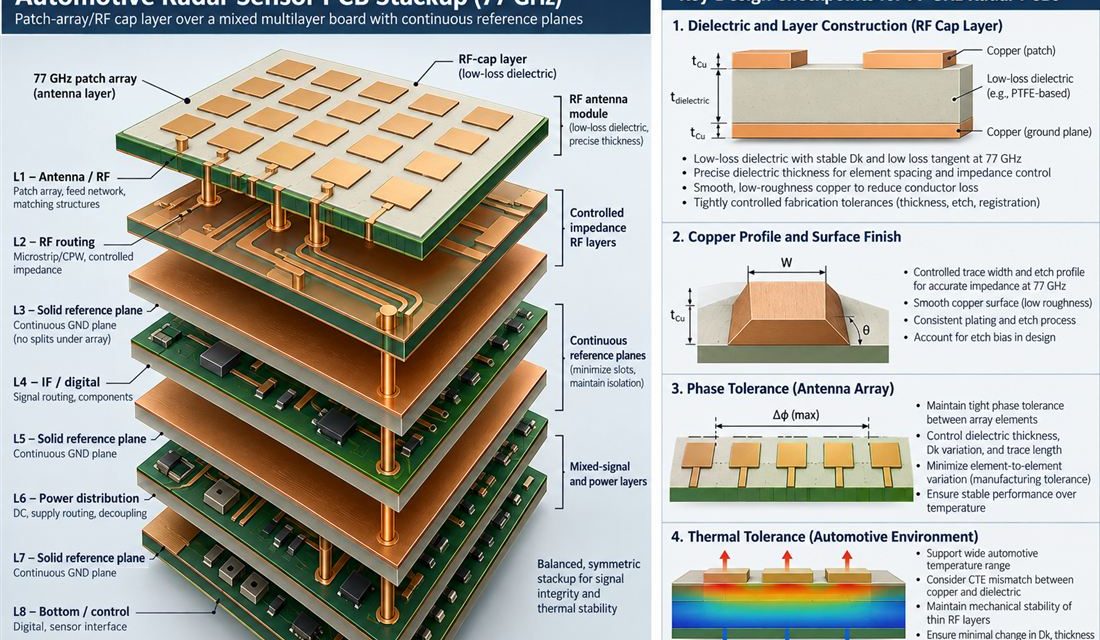
Radar PCB: Design Principles, Materials, Manufacturing Challenges & Key Applications High-speed PCBs stand at the top of modern circuit-board technology, spanning digital high-speed, mixed-signal, and RF/microwave categories. Among these, RF and microwave PCBs operate at the highest frequencies, making them essential for advanced applications—especially RADAR (Radio Detection and Ranging). Because Radar PCBs frequently host a...

ADAS PCB Layout Guidelines for Automotive Radar Systems: Best Practices for High-Frequency Design

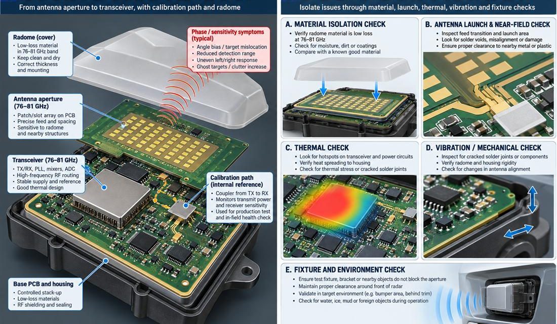
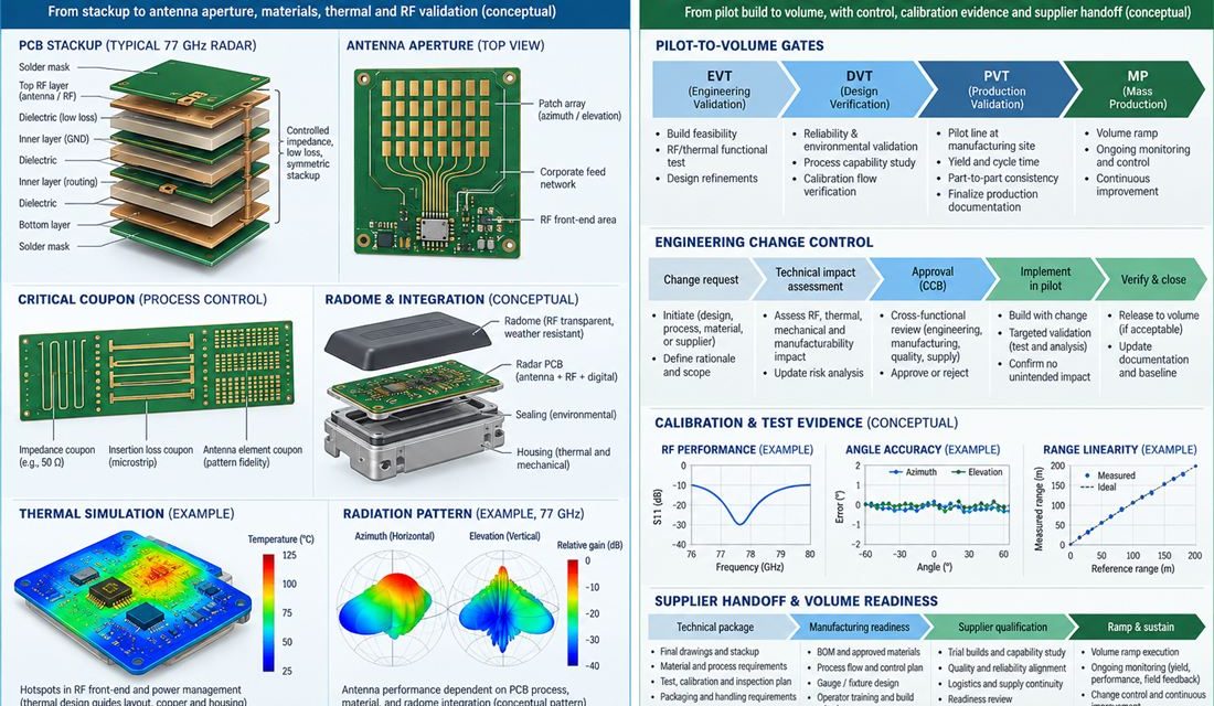
Advanced Driver Assistance Systems (ADAS) depend on high-performance automotive radar PCBs operating primarily at 77 GHz (and extending to 79 GHz) to deliver critical functions such as adaptive cruise control, automatic emergency braking, blind-spot detection, lane-change assistance, and 4D imaging. At these millimeter-wave frequencies, even minor imperfections in ADAS PCB layout can cause significant signal...