HomeTag

Automotive Radar - KKPCB

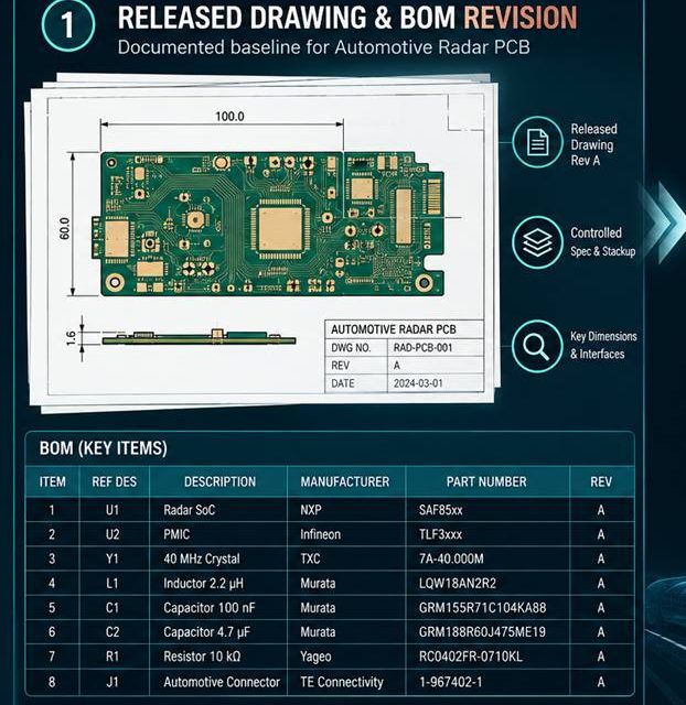
The Change-Control File Behind a Production-Ready Automotive Radar PCB

Automotive Radar PCB production release begins when design evidence, supplier capability, and change control agree. The last ten percent of a board program is rarely a single design change. It is the point where a prototype stackup, a supplier process, a connector choice, and an enclosure must become one controlled release. For front and corner...
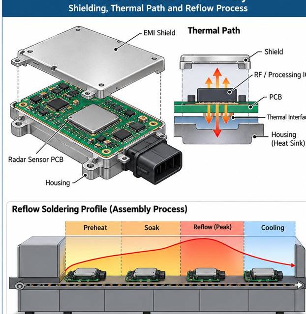
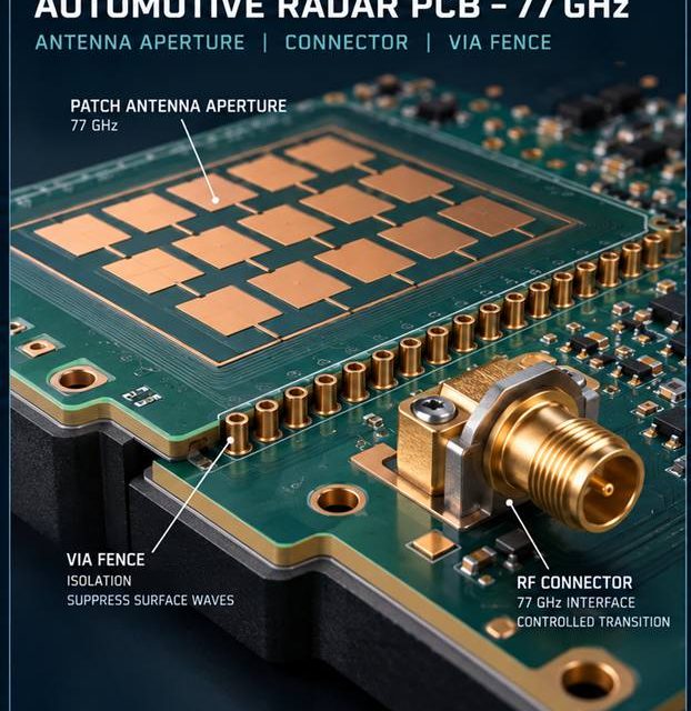
Protecting RF Geometry During Automotive Radar PCB Assembly

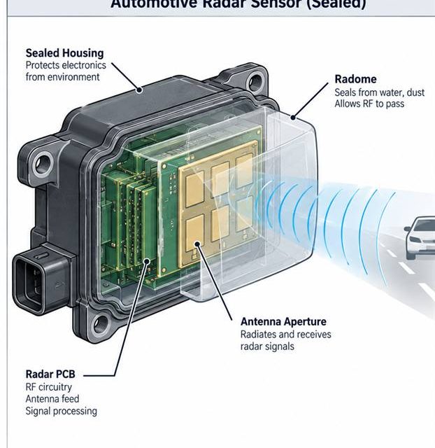
Automotive Radar PCB assembly release begins by treating heat, solder, cleaning, and mechanical force as RF variables. An RF board can leave fabrication within drawing limits and still change during paste printing, reflow, shielding, cleaning, or mechanical assembly. That risk is amplified in front and corner radar sensors exposed to vibration, temperature cycling, radome constraints,...

Controlling the 77 GHz Launch on an Automotive Radar PCB

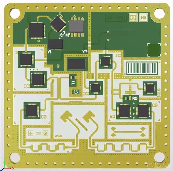
Automotive Radar PCB launch design begins with a complete three-dimensional signal and return path. The boundary between a board and a connector, coax, antenna, or shield is where a clean schematic becomes a three-dimensional electromagnetic problem. In front and corner radar sensors exposed to vibration, temperature cycling, radome constraints, and strict end-of-line calibration, that boundary...

Building an Automotive Radar PCB Stackup That Survives Thermal History

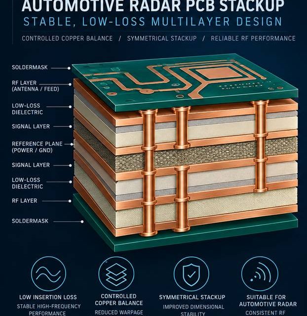
Automotive Radar PCB stackup release begins by making every electromagnetic and manufacturing assumption visible. Stackup discussions fail when the drawing lists layer names but not the electromagnetic and manufacturing assumptions behind them. In front and corner radar sensors exposed to vibration, temperature cycling, radome constraints, and strict end-of-line calibration, the board must carry RF energy,...

Finding the Root Cause of Drift in an Automotive Radar PCB

Automotive Radar PCB fault isolation begins at the physical boundary where the symptom is reproduced. A front and corner radar sensors exposed to vibration, temperature cycling, radome constraints, and strict end-of-line calibration can pass a schematic review and still fail in the chamber, the enclosure, or the vehicle. The failure often appears as a receiver...

Reliability and Phase Consistency Validation of PTFE PCBs in Automotive Radar Front-End Modules

1. Engineering Overview / Abstract   High-frequency automotive radar front-end modules operating at 77–79 GHz demand PCB substrates that combine low insertion loss with precise phase stability under harsh environmental conditions. PTFE PCB laminates, with a dielectric constant Dk = 2.10 ± 0.03 and loss tangent Df = 0.0007 @10 GHz, provide the electrical and...

Reliability and Phase Stability Enhancement of Ceramic PCBs in Automotive Radar and ADAS Sensor Modules

1. Engineering Overview   As modern vehicles advance toward full autonomy, automotive radar and ADAS (Advanced Driver-Assistance Systems) demand exceptional signal fidelity and real-time response under wide temperature ranges and mechanical stress. Within these radar transceiver modules, Ceramic PCB substrates play a pivotal role in ensuring phase stability, low dielectric loss, and long-term thermal reliability. ...

Low-Loss Transmission and Impedance Control of Megtron 7 PCBs in Automotive mmWave Radar Systems

1. Engineering Overview   Automotive mmWave radar modules for advanced driver-assistance systems (ADAS) require precise RF signal propagation with minimal loss and stable impedance across multilayer PCBs. Trace density and high-frequency operation introduce challenges in maintaining signal integrity and   crosstalk suppression. Megtron 7 PCBs, with Dk = 3.40 ±0.02 and Df = 0.0018 @ 10...

Achieving Low-Loss Transmission and Thermal Reliability with Megtron 6 PCBs in Automotive Radar and ADAS Control Units

1. Low-Loss Signal Requirements in Automotive Radar Systems   Automotive radar and ADAS modules operate at 77–79 GHz frequencies, demanding minimal insertion loss and consistent phase integrity. Dense multilayer routing, compact stackups, and exposure to thermal cycles present challenges for signal fidelity.  Megtron 6 PCBs, with Dk = 3.45 ±0.02 and Df = 0.002 @10...

Achieving Low-Loss Transmission and Thermal Reliability with Taconic TLY-5 PCBs in Automotive mmWave Radar Systems

1. Engineering Overview / Abstract   Automotive radar technology operating in the 76–81 GHz band demands printed circuit boards with extremely low dielectric loss, phase stability, and high thermal endurance.  Taconic TLY-5 PCB laminates—featuring a Dk of 2.20 ± 0.02 and Df of 0.0009 @ 10 GHz—offer a robust foundation for mmWave antenna arrays, signal...