HomeCategory

PCB Materials | FR-4, High-Frequency, Low-Loss & Heavy Copper - KKPCB

Satellite PCB Vacuum Reliability: Manage Outgassing, Cleanliness, and Material Controls

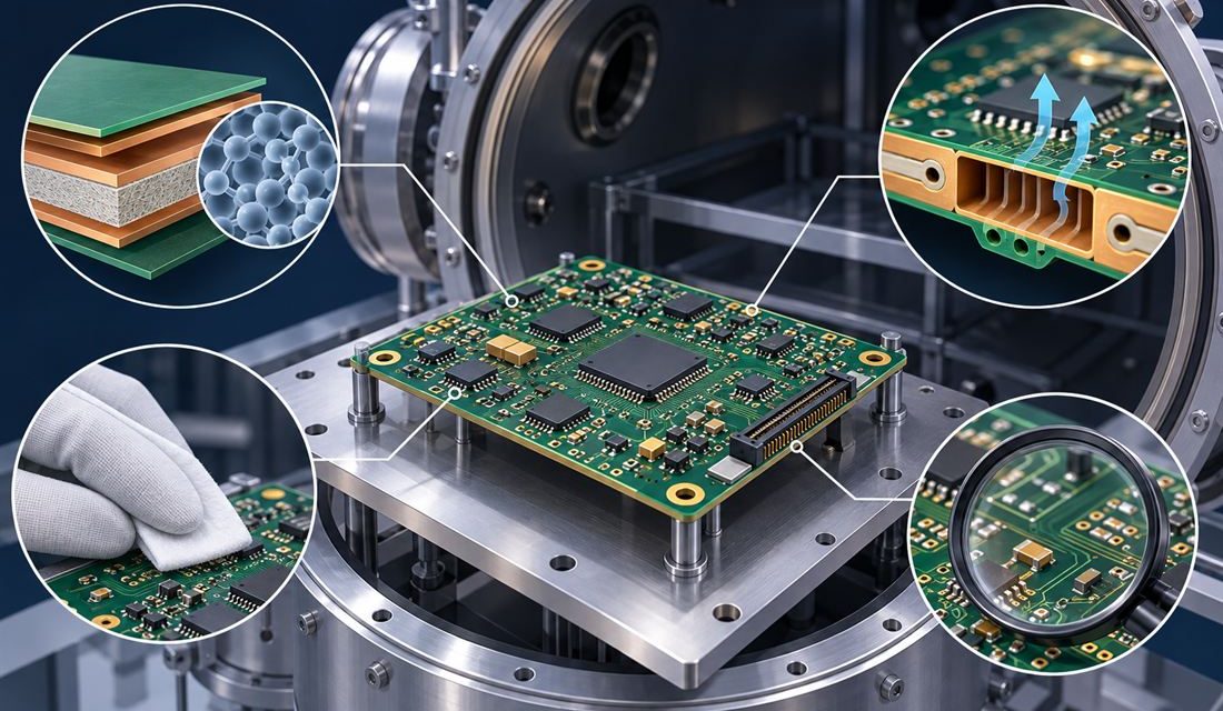
A Satellite PCB can pass electrical inspection on the bench and still become a contamination source after launch. In vacuum, volatile compounds have no convective path away from the assembly; they migrate and may condense on colder optical, RF, thermal-control, or detector surfaces. The engineering question is therefore not simply whether a laminate has a...
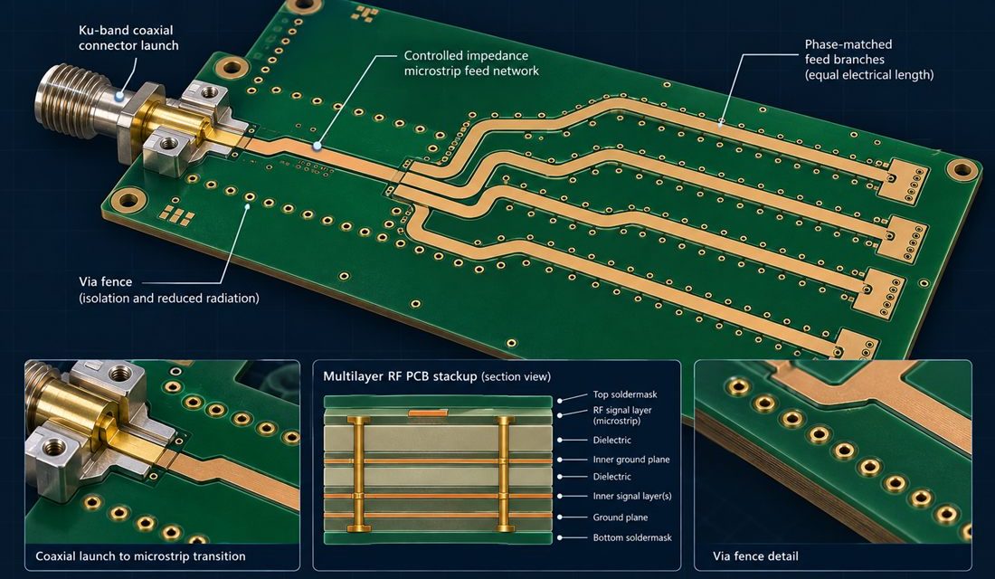
Satellite PCB Ku-Band Feed Networks: Preserving Phase Balance from Launch to Antenna

A Satellite PCB Ku-band feed network is often released as a routing problem, then fails as an integration problem. The electrical design may show equal-length branches and an acceptable nominal impedance, yet the assembled payload can lose phase balance when a connector launch, via fence, housing wall, or harness datum moves the return path. At...

Satellite PCB Thermal Drift: Managing CTE, Copper Density, and Chassis Interfaces

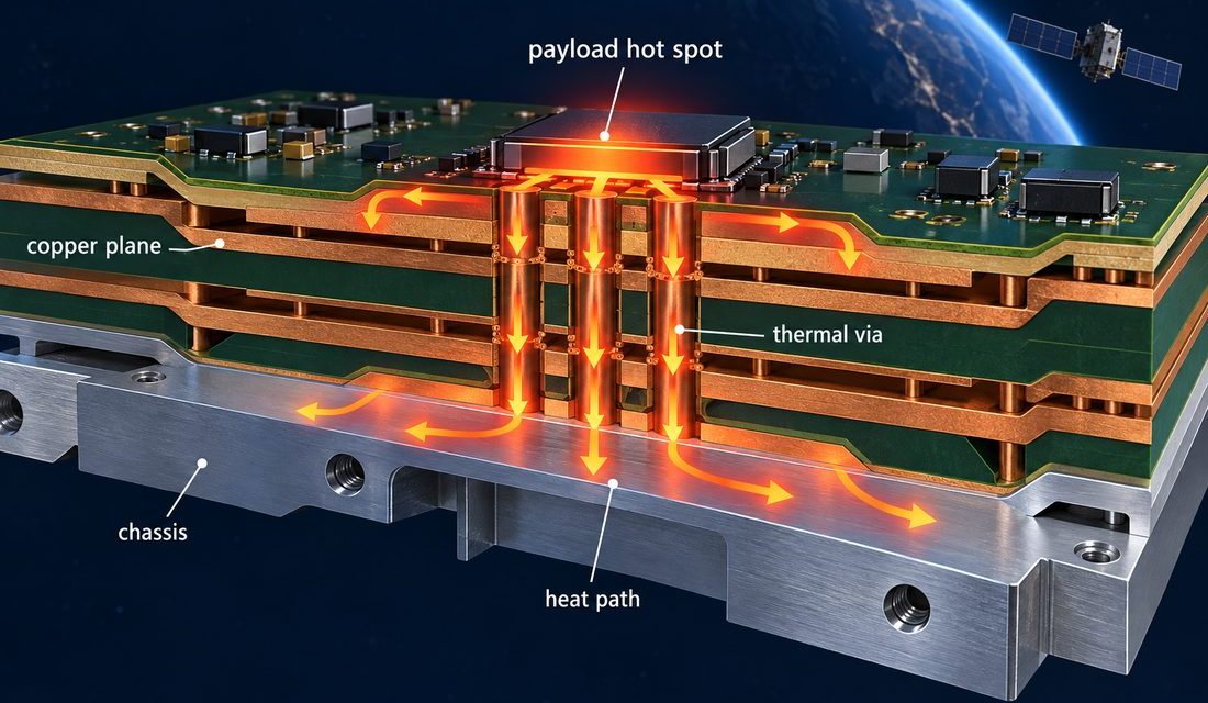
Satellite PCB thermal drift becomes a mission risk when a board is treated as a flat electrical drawing instead of a constrained mechanical and thermal assembly. A payload can meet its schematic targets and still show connector strain, oscillator frequency movement, or intermittent solder fatigue after repeated hot-cold transitions. This Satellite PCB thermal drift problem...

Satellite PCB Radiation Design for LEO Avionics: Dielectrics, Planes, and Shielded Returns

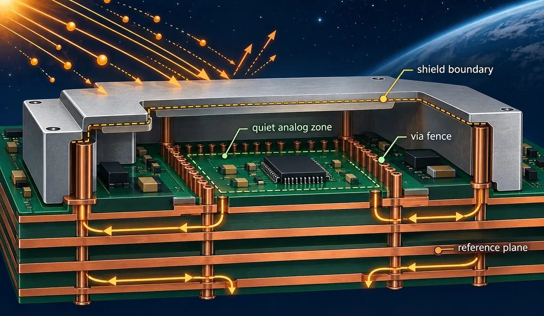
Satellite PCB radiation design for low-Earth-orbit avionics is often reviewed too late as a materials choice. The difficult question is not whether a board can route a signal; it is whether the dielectric, copper stack, enclosure bond, and return current still behave predictably after radiation exposure, thermal cycling, launch handling, and repeated engineering changes. A...

Ku/Ka Satellite PCB Launch Design: Taming Connector and Via Transitions at 30 GHz

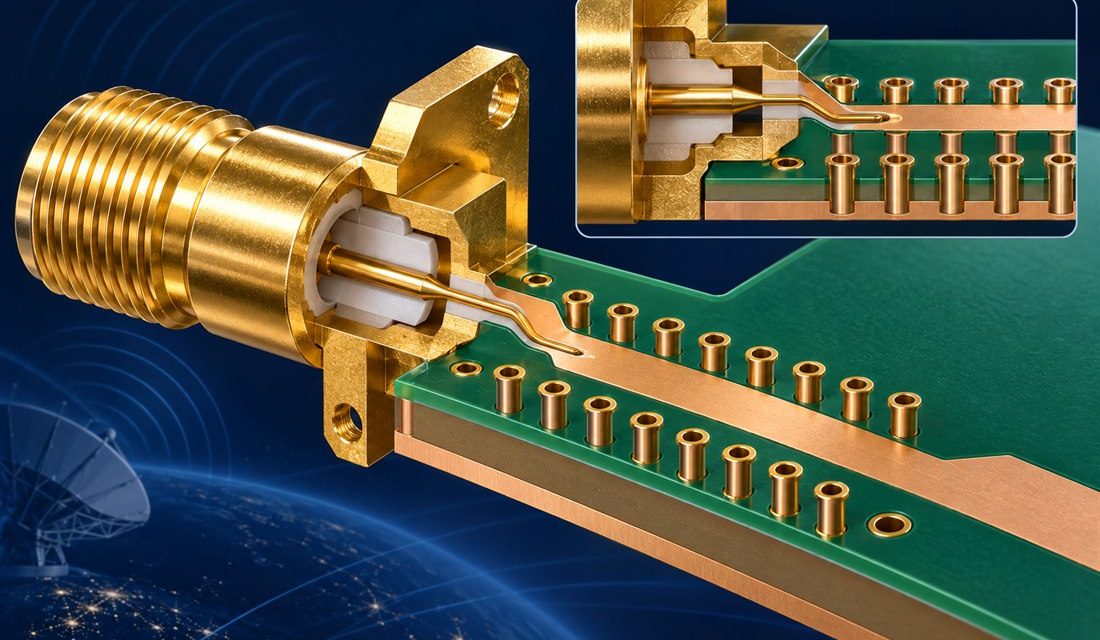
For Satellite PCB launch design, a Ku/Ka payload can meet its schematic targets and still lose margin at the board edge. The connector, launch pad, reference plane, via field, and enclosure datum form one electromagnetic interface. The Satellite PCB release must hold that board-to-enclosure datum constant across design and manufacturing. At 30 GHz, even a...

Aerospace PCB RF Phase Stability: Practical AD9361 Clock Review

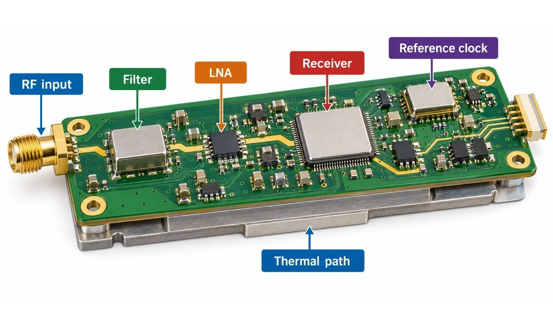
An Aerospace PCB for a navigation receiver must prevent small phase changes from becoming timing, bearing, or coherent-combining errors long before the board shows an obvious electrical failure. Engineers searching for an Aerospace PCB phase-stability solution should begin by separating clock behavior, RF path mismatch, thermal gradients, and calibration repeatability. The board cannot correct an...

Robotics PCB Serviceability: Designing the Board for Repeatable Replacement

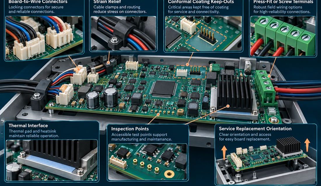
Table of Contents Why serviceability belongs in the PCB release Treat connectors and strain relief as one system Protect thermal and coating interfaces Make inspection repeatable Close the maintenance handoff A robot controller is rarely repaired on a quiet laboratory bench. A technician works inside a cabinet or joint enclosure, disconnects a harness, replaces a...

Robotics PCB Vision and Force Sensing: Keeping Mixed Signals Honest

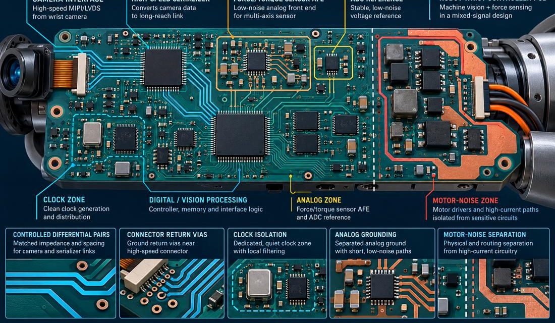
Table of Contents Why vision and force signals fight on one board Partition clocks, analog, and motor noise Protect high-speed launches Calibrate the sensor chain Release a wrist module A robot wrist that combines a camera, a force/torque sensor, and a motor interface has three different definitions of “clean data.” The camera needs controlled differential...

Robotics PCB Safety Isolation: Making the Barrier Manufacturable

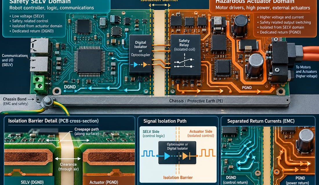
Table of Contents Treat the isolation boundary as a system boundary Turn creepage into layout geometry Keep EMC current out of logic return Verify the fault state Release evidence without overclaiming A robot controller can pass a functional motion test and still carry a dangerous layout ambiguity. The problem appears where low-voltage logic, safety I/O,...

Robotics PCB Encoder Feedback: Keeping A/B/Z Phase Intact

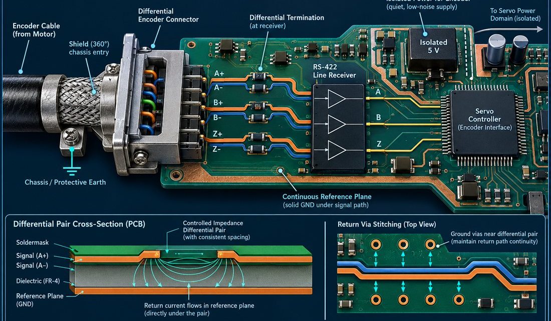
Table of Contents Why encoder faults masquerade as software bugs Keep A/B/Z pairs phase-stable Close the shield and return path Test cable length and temperature Release feedback with evidence When a robot axis occasionally reports a position jump, the first suspect is often firmware. Yet many intermittent encoder faults are created at the connector launch,...