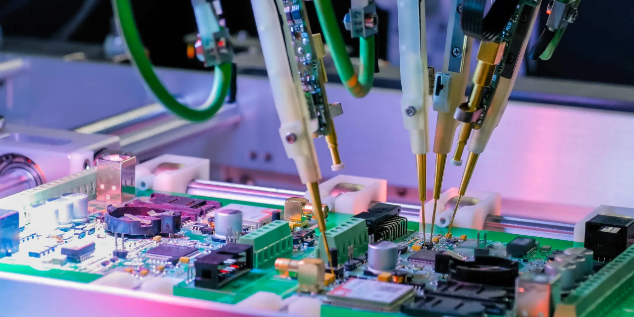
PCB manufacturing - KKPCB
 
HomeTag

PCB manufacturing - KKPCB

RF Reliability Testing and Environmental Endurance of RO4003C PCBs for Automotive and Aerospace Systems

Reliability Challenges in High-Frequency Applications In demanding industries such as automotive electronics and aerospace systems, RF PCB reliability is critical for ensuring long-term system performance under extreme operating conditions. As high-frequency PCB applications continue to expand—especially in radar systems, satellite communication, and advanced driver-assistance systems (ADAS)—materials like RO4003C PCB laminates are widely used for their...

Ensuring PCB Reliability Through Burn-in Testing — How KKPCB Guarantees Long-Term Performance

Ensuring PCB Reliability Through Burn-in Testing — How KKPCB Guarantees Long-Term Performance In high-performance electronics, reliability isn’t a luxury — it’s a requirement. At KKPCB, every printed circuit board that leaves our production line is expected to perform consistently under demanding real-world conditions. One of the most critical steps in achieving that standard is our...

Blind and Buried Vias in PCB Design – Advanced HDI Interconnection Solutions

Blind and Buried Vias in PCB Design — Structure, Function, and Manufacturing Insights As the miniaturization of electronic components continues to accelerate, PCB designs must accommodate finer pitch components and higher circuit densities, especially in advanced mobile, communication, and computing applications. One of the critical technologies enabling this evolution is the use of blind and...

Explore how KKPCB engineers world-class radar PCBs for automotive, aerospace, and defense applications. Learn about design techniques, RF materials, and manufacturing precision for frequencies up to 77 GHz.

Radar PCB Overview Radar PCBs represent the pinnacle of high-frequency circuit design, bridging advanced RF engineering and precise manufacturing. These specialized boards operate in the 1 GHz – 77 GHz range, demanding exceptional signal integrity, low loss materials, and extreme reliability — especially in mission-critical applications like automotive radar, aerospace, and defense. KKPCB has extensive...

SMT Assembly Instructions: A Beginner’s Guide

Electronic devices have transformed our lives, from smartphones to electric vehicles, all thanks to continuous innovation and advancements in technology. At the heart of these devices are printed circuit boards (PCBs) that are meticulously manufactured, assembled, and packaged to deliver the final products we rely on. This article explores the PCB Surface Mount Technology (SMT) assembly process,...

SMT Assembly vs Through-Hole Assembly: Advantages and Disadvantages

When it comes to assembling Printed Circuit Boards (PCBs), there are two primary technologies: Surface Mount Technology (SMT) assembly and Through-Hole Technology (PTH) assembly. Understanding their differences, advantages, and disadvantages is crucial for selecting the best option for your PCB-based project. This guide by Viasion experts provides a comprehensive comparison to help you make an informed decision. What...

BGA Assembly: Beginner’s Guide to Ball Grid Array Assembly

Why BGA Assembly Is Critical in Modern PCB Design As electronic devices move toward miniaturization, high-speed performance, and high pin-count integration, the Ball Grid Array (BGA) assembly has become a mainstream packaging technology in: Microprocessors (CPU/GPU) FPGAs High-speed communication ICs Memory devices (DDR, LPDDR) Compared with traditional packages (QFP, SOP), BGA offers: Higher I/O density...

How to Remove Flux from PCB?

During PCB soldering and PCB assembly (PCBA), flux is widely used to ensure strong and reliable electrical connections. However, removing flux from PCB after soldering is equally important. Excess flux residue on PCB can lead to signal interference, corrosion, leakage current, and long-term reliability issues. This guide explains how to remove flux from PCB, covering...

Single-layer FPC, double-layer FPC and multi-layer FPC in PCB manufacturing

Differences between single-layer FPC, double-layer FPC and multi-layer FPC Multi-layer FPC Multi-layer FPC is to stack three or more layers of single-sided or double-sided flexible circuits together, and make metallized holes through drilling, electroplating and other processes to achieve conductive paths between different layers, so no complex welding process is required. Multi-layer circuits have great functional...