HomeCategory

Advanced Engineering Technologies for PCB & PCBA Solutions - KKPCB

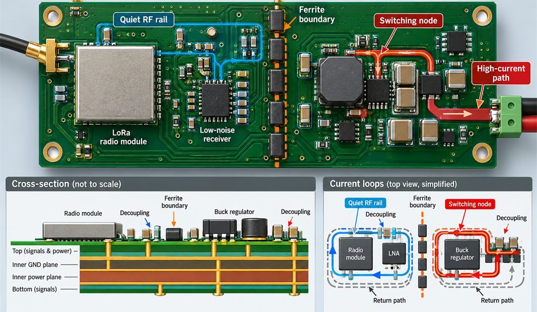
The LoRa PCB Power Path That Keeps a Remote Sensor from Going Deaf

Table of Contents Why a quiet receiver can fail under transmit load Partition the power path before routing Keep decoupling and shielding stable through assembly Release power integrity as a production characteristic A remote node built around a LoRa PCB may pass a bench range check and then miss packets when its own transmitter, sensor...
Why a LoRa PCB Loses Sensitivity When the Gateway Ground Plane Moves

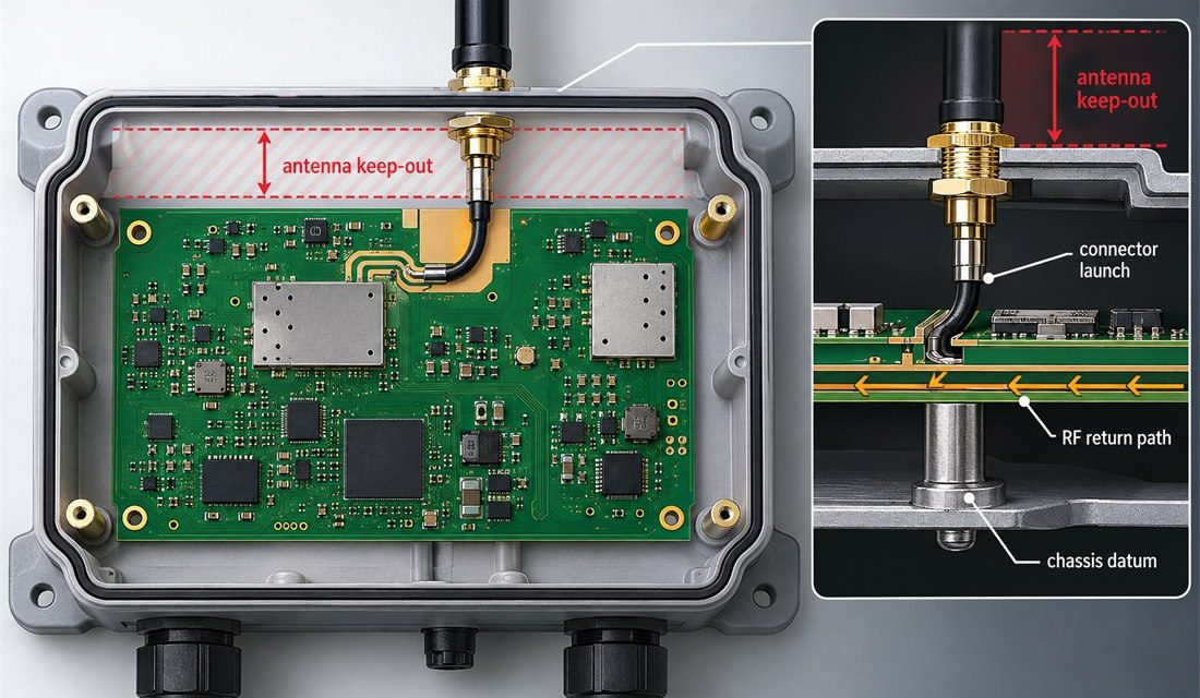
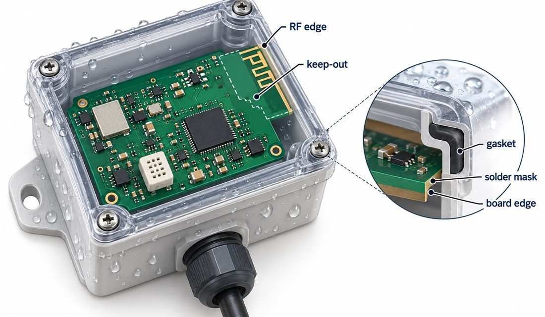
Table of Contents The gateway symptom that points to the board Freeze the antenna boundary and return path Control the connector launch and panel edge Release a repeatable gateway build A LoRa PCB gateway can appear to have a healthy radio, a valid firmware image, and a correctly tuned antenna yet lose sensitivity after the...

When a Zigbee PCB Drifts After Humidity, Cleaning, and Conformal Coating

Table of Contents Why a stable radio drifts after environmental processing Control moisture, residues, and the antenna boundary Design the coating process around RF and test access Release evidence for production and field support A Zigbee PCB can pass a clean-room range check and still drift after humidity exposure, aqueous cleaning, or conformal coating. Engineers...

Why a Zigbee PCB Passes Layout Review but Fails at Panelization

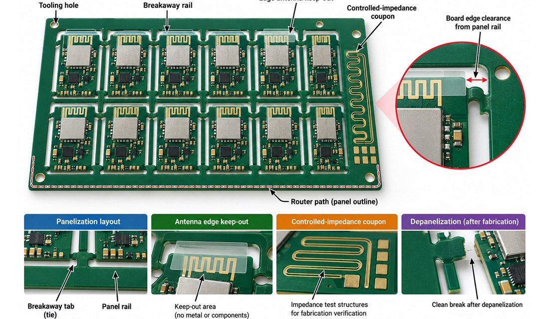
Table of Contents Treat the panel as an RF state Protect the antenna edge and return path Control tabs, rails, and depanelization Release evidence for assembly and test A Zigbee PCB can pass a single-board layout review and still lose repeatability when it enters a manufacturing panel. Breakaway rails, tooling holes, router paths, copper balance,...

How to Hold Connector and Thermal Quality in Automotive Module PCB Assembly

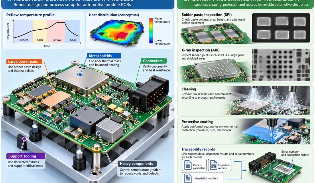
Automotive Module PCB — Fabrication can meet a drawing and assembly can still move the electrical result. Paste height, reflow warpage, shield force, cleaning chemistry, heat spreaders, and connector rework all act on vehicle modules that package communication, power, sensing, and control functions behind a connector-rich housing with tight mechanical and service constraints. This production...

Finding the Physical Cause of Drift in an Automotive High Frequency PCB

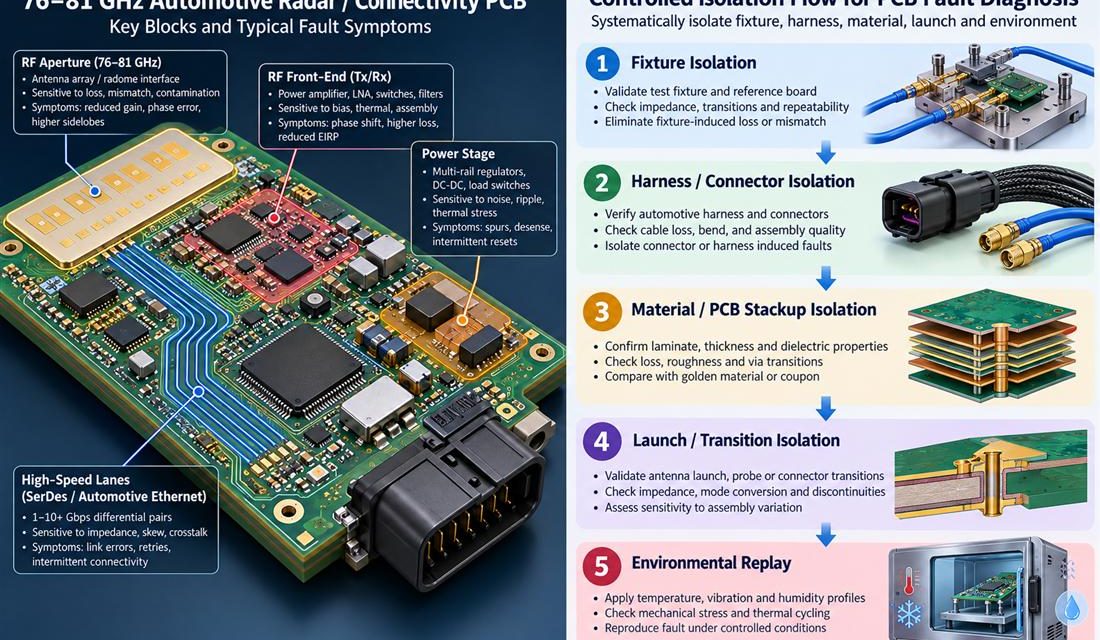
Automotive High Frequency PCB — A vehicle program can report an intermittent reset, a communication dropout, a radar sensitivity loss, or a calibration value that moves only after the enclosure is closed. That symptom is not yet a PCB diagnosis. On a Automotive High Frequency PCB, the board shares its boundary with a harness, connector,...

When an Automotive Electronics PCB Fails Only in the Vehicle: A Root-Cause Workflow

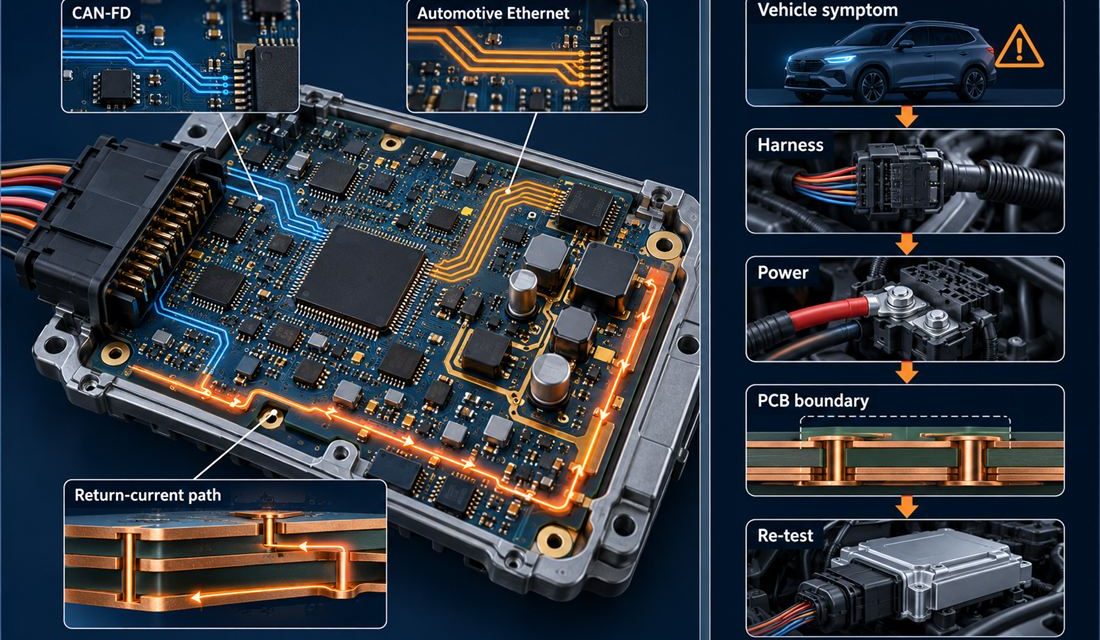
Automotive Electronics PCB — A vehicle program can report an intermittent reset, a communication dropout, a radar sensitivity loss, or a calibration value that moves only after the enclosure is closed. That symptom is not yet a PCB diagnosis. On a Automotive Electronics PCB, the board shares its boundary with a harness, connector, shield, heat...

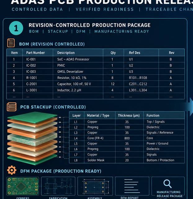
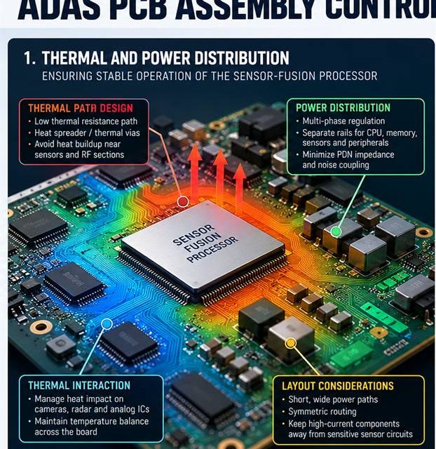
An Assembly Control Plan for High-Reliability ADAS PCB Production

ADAS PCB assembly release begins by treating heat, solder, cleaning, and mechanical force as RF variables. An RF board can leave fabrication within drawing limits and still change during paste printing, reflow, shielding, cleaning, or mechanical assembly. That risk is amplified in camera, radar, and domain-controller electronics that must keep data paths deterministic while surviving...

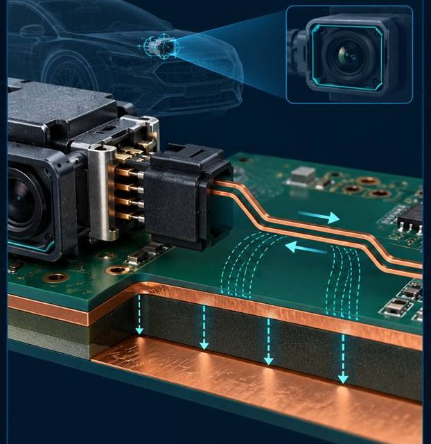
Keeping High-Speed Sensor Links Quiet Through an ADAS PCB Connector Transition

ADAS PCB launch design begins with a complete three-dimensional signal and return path. The boundary between a board and a connector, coax, antenna, or shield is where a clean schematic becomes a three-dimensional electromagnetic problem. In camera, radar, and domain-controller electronics that must keep data paths deterministic while surviving automotive assembly and service constraints, that...