HomeCategory

PCB Materials | FR-4, High-Frequency, Low-Loss & Heavy Copper - KKPCB

Ceramic PCB Antenna Cavities at mmWave: Controlling Geometry Before the First Build

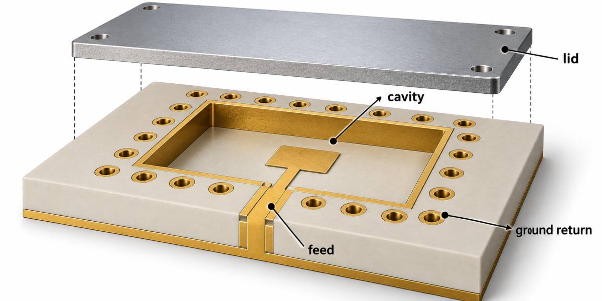
At mmWave frequencies, the cavity, copper edge, connector launch, and antenna clearance become part of the circuit. A Ceramic PCB is often selected for its dimensional stability and integration potential, yet a cavity that is only slightly too deep or a ground fence that is interrupted by a tooling keep-out can move the resonance enough...
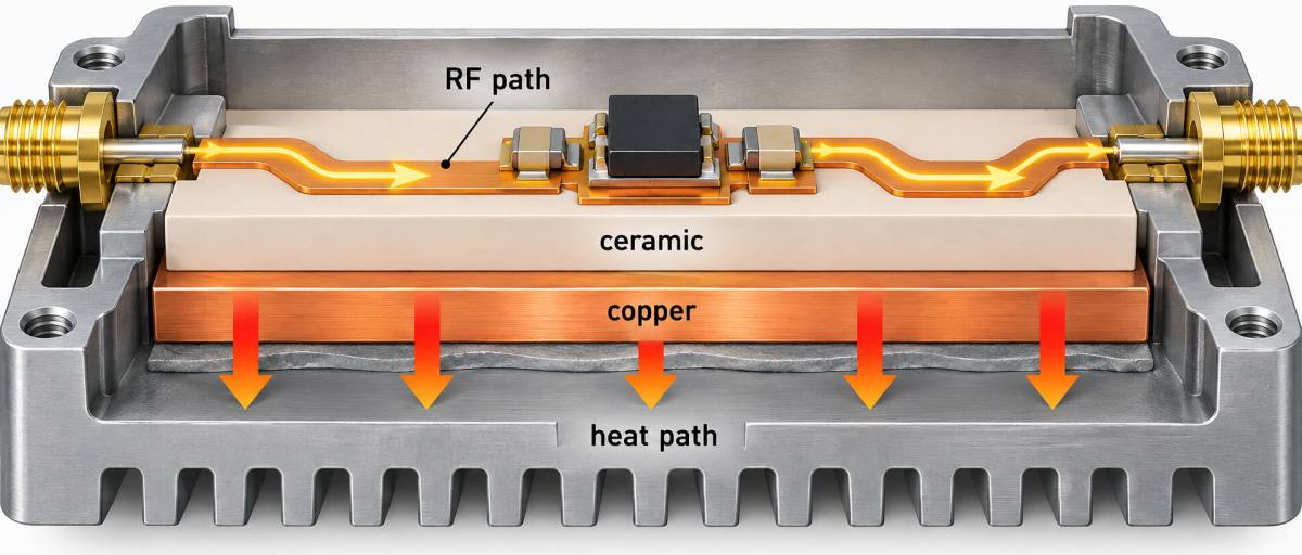
Ceramic PCB Thermal Interfaces for High-Power RF Modules: A Release Review

A high-power RF module can meet its electrical target and still fail in the field because the heat path was never released as a complete system. A Ceramic PCB changes the design conversation: the ceramic substrate, copper pattern, attach method, via or metallized interface, and the enclosure all share the same thermal boundary. The project...

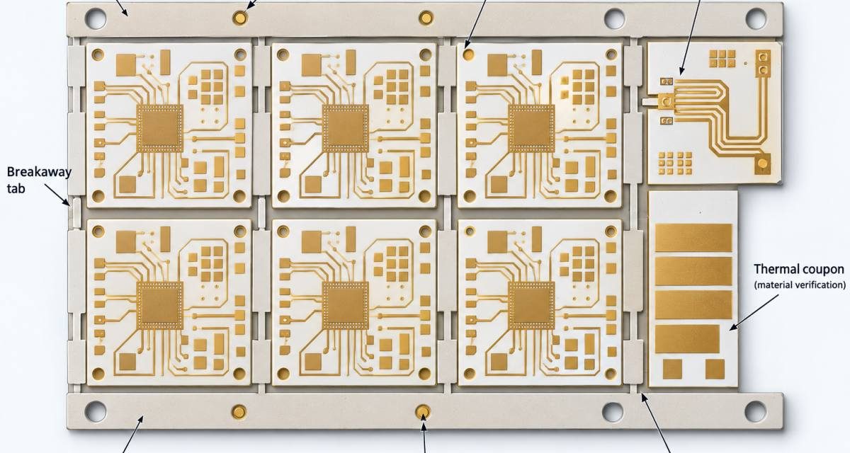
Ceramic PCB DFM and Procurement Release: Avoiding First-Build Surprises

Ceramic PCB programs often move from concept to purchase order faster than the manufacturing package matures. The layout may be complete, but the supplier still lacks a defined panel, edge condition, metallization note, inspection plan, or approved substitute rule. That gap creates schedule risk because a ceramic panel is not interchangeable with a conventional laminate...

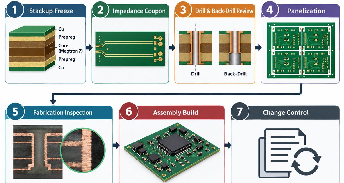
Megtron 7 PCB DFM Release: Panelization, Coupons, and ECO Control Before Volume Build

The most expensive Megtron 7 PCB problem is often a release problem, not a material problem. A prototype may route correctly, yet the volume panel has no representative coupon, uneven copper, an impractical depanelization rail, or an ECO that quietly changes the impedance construction. A useful DFM gate turns the electrical intent into a package...

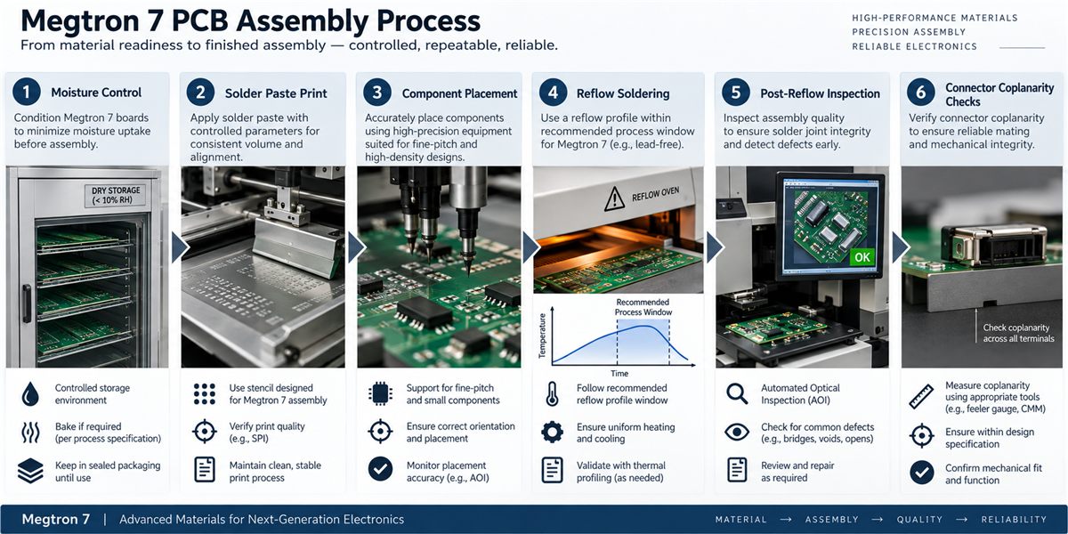
Megtron 7 PCB Assembly: Moisture, Reflow, and Coplanarity Controls for High-Speed Modules

A high-speed board can pass fabrication inspection and still lose performance during assembly. Moisture exposure, an unsuitable reflow window, connector coplanarity, or residue under a shield can change the mechanical position of a launch and weaken a controlled return path. A production-ready Megtron 7 PCB connects material handling to RF and signal-integrity requirements. Table of...

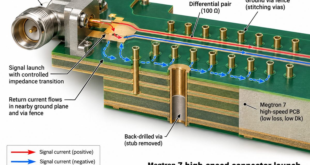
Megtron 7 PCB Connector Launches: A Back-Drill and Ground-Return Review for Multi-Gigabit Ports

Connector launches often become the hidden bottleneck in a high-speed program. The laminate may have a low loss tangent, but an unused barrel stub, a broken reference plane, or an asymmetric ground-via pattern can dominate the transition. Treat every Megtron 7 PCB as a small RF structure with its own geometry, datum, and verification plan....

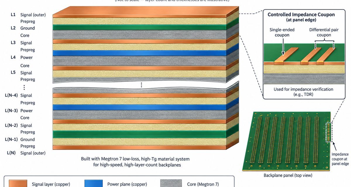
How to Freeze a Megtron 7 PCB Stackup When Layer Count and Impedance Must Move Together

A Megtron 7 PCB stackup must be frozen as an electrical and manufacturing contract before layer count or impedance changes are approved. High-layer-count digital boards rarely fail because an engineer forgot to draw a trace. They fail when a late layer move changes dielectric thickness, resin distribution, or reference-plane continuity and the impedance model is...

Megtron 7 PCB Copper Profile and Glass-Weave Control for Long Backplane Channels

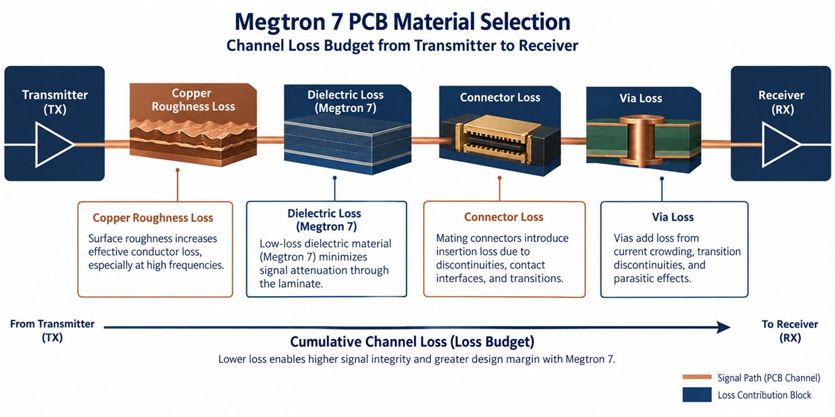
A long backplane channel can fail a design review even when the laminate choice looks correct on paper. The usual problem is not one dramatic defect; it is the accumulation of copper profile loss, dielectric loss, connector discontinuity, via loss, and local glass-weave skew. A useful Megtron 7 PCB project therefore starts with a channel...

Megtron 6 PCB DFM Release: The Production Checks That Protect High-Speed Yield

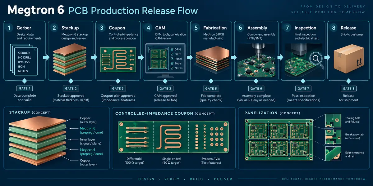
The released Megtron 6 PCB construction is the reference for the DFM package. Any supplier change to a Megtron 6 PCB must carry the same stackup and coupon revision, so procurement can compare capacity without changing electrical intent. Megtron 6 PCB DFM release work is where a high-speed design becomes a repeatable production definition. A...

Megtron 6 PCB Assembly: A Reflow and Connector-Launch Plan for High-Speed Modules

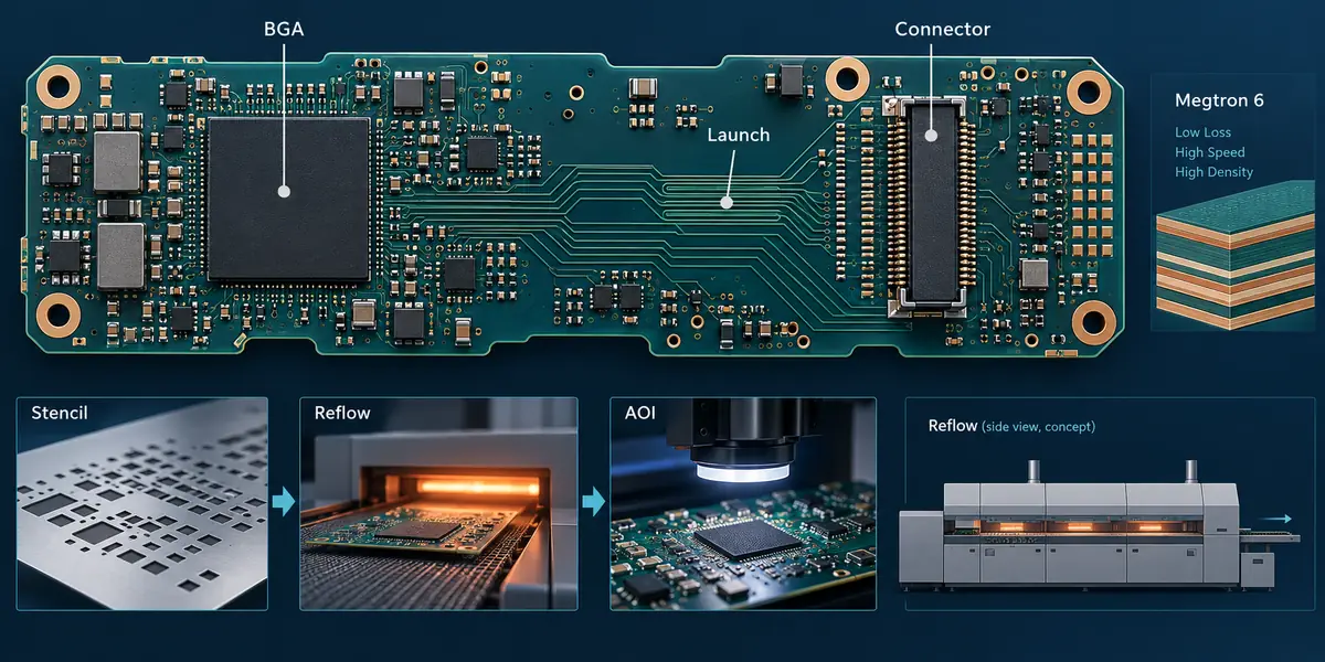
The Megtron 6 PCB connector launch remains the shared datum for SI and assembly inspection. The production Megtron 6 PCB callout should travel with the reflow and inspection package. A connector change on a Megtron 6 PCB is an electrical and assembly change, not only a mechanical edit. For the release team, a Megtron 6...