HomeCategory

PCB Materials | FR-4, High-Frequency, Low-Loss & Heavy Copper - KKPCB

Designing the Connector Launch of an Automotive High Frequency PCB

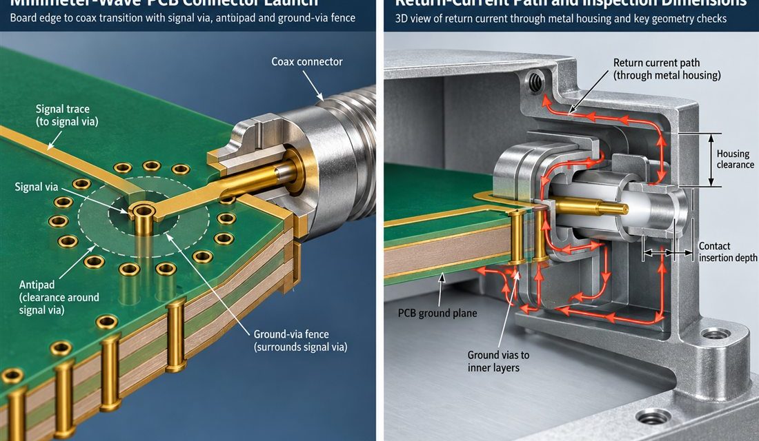
Automotive High Frequency PCB — The connector, coax, antenna, sensor flex, or board edge is where a schematic becomes a three-dimensional part. In high-frequency automotive radar and connectivity boards where fast edges, 76–81 GHz channels, and a constrained metal housing share the same release, that interface also has to survive mating force, housing tolerances, and...
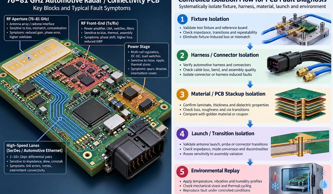
Finding the Physical Cause of Drift in an Automotive High Frequency PCB

Automotive High Frequency PCB — A vehicle program can report an intermittent reset, a communication dropout, a radar sensitivity loss, or a calibration value that moves only after the enclosure is closed. That symptom is not yet a PCB diagnosis. On a Automotive High Frequency PCB, the board shares its boundary with a harness, connector,...

What the Assembly Line Can Change on a Radar PCB

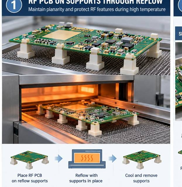
Radar PCB assembly release begins by treating heat, solder, cleaning, and mechanical force as RF variables. An RF board can leave fabrication within drawing limits and still change during paste printing, reflow, shielding, cleaning, or mechanical assembly. That risk is amplified in short-range and imaging radar front ends where antenna phase error, launch repeatability, and...

A Ground-Return Strategy for Radar PCB Antenna Transitions

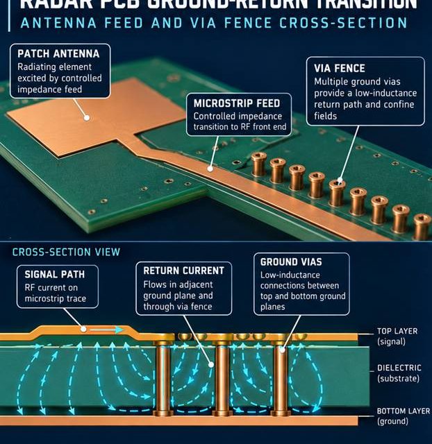
Radar PCB launch design begins with a complete three-dimensional signal and return path. The boundary between a board and a connector, coax, antenna, or shield is where a clean schematic becomes a three-dimensional electromagnetic problem. In short-range and imaging radar front ends where antenna phase error, launch repeatability, and thermal drift all affect detection margin,...

How a Radar PCB Stackup Preserves Phase Consistency Across the Array

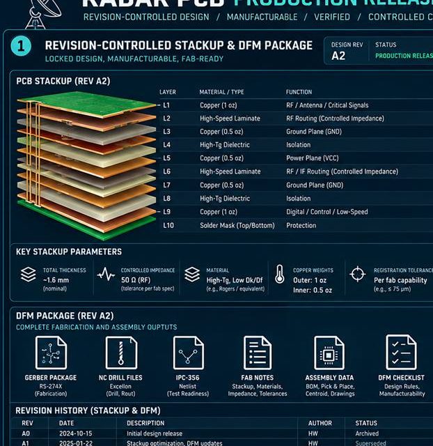
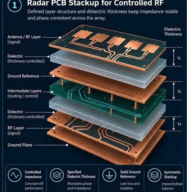
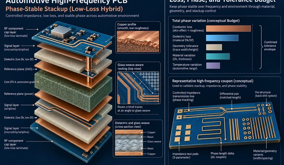
Radar PCB stackup release begins by making every electromagnetic and manufacturing assumption visible. Stackup discussions fail when the drawing lists layer names but not the electromagnetic and manufacturing assumptions behind them. In short-range and imaging radar front ends where antenna phase error, launch repeatability, and thermal drift all affect detection margin, the board must carry...

From EVT Evidence to Volume Release for a 5G Module PCB

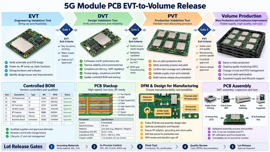
5G module PCB production release begins when design evidence, supplier capability, and change control agree. The last ten percent of a board program is rarely a single design change. It is the point where a prototype stackup, a supplier process, a connector choice, and an enclosure must become one controlled release. For compact radio modules...

Keeping RF Performance Intact Through 5G Module PCB Assembly

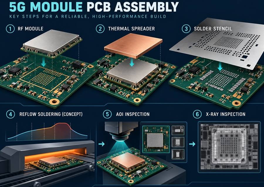
5G module PCB assembly release begins by treating heat, solder, cleaning, and mechanical force as RF variables. An RF board can leave fabrication within drawing limits and still change during paste printing, reflow, shielding, cleaning, or mechanical assembly. That risk is amplified in compact radio modules used in private 5G radios, fixed-wireless units, and edge...