HomeTag

automotive radar sensor - KKPCB

Keeping Radar Geometry Stable Through Automotive Radar Sensor PCB Assembly

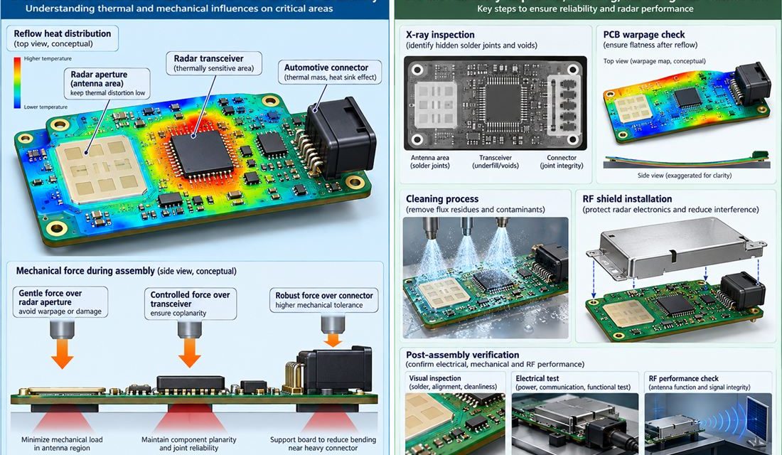
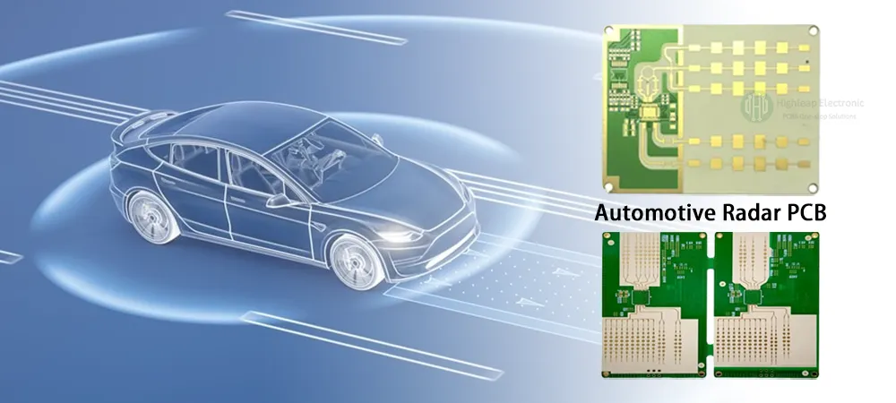
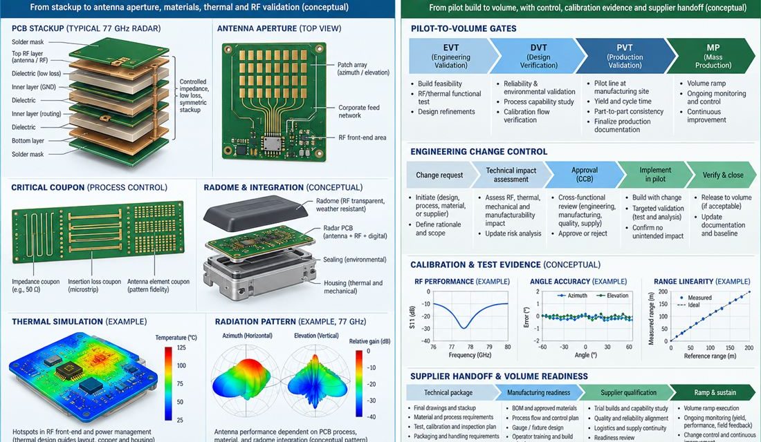
Automotive Radar Sensor PCB — Fabrication can meet a drawing and assembly can still move the electrical result. Paste height, reflow warpage, shield force, cleaning chemistry, heat spreaders, and connector rework all act on front, corner, and short-range radar sensor boards using a 76–81 GHz antenna aperture, transceiver, processor, and sealed housing. This production guide...

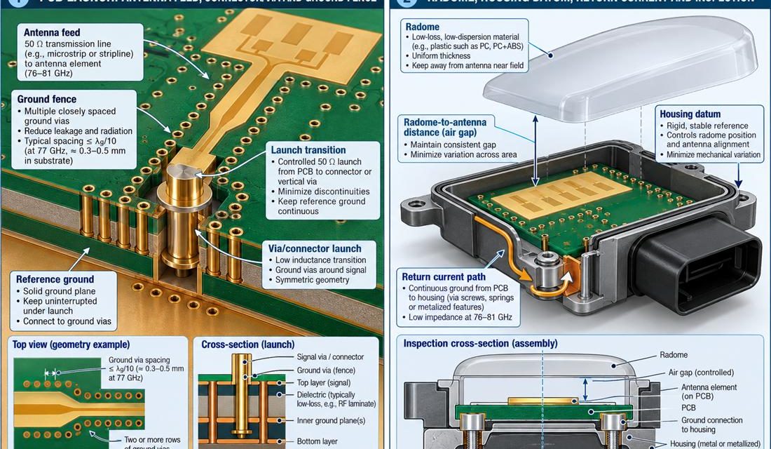
Controlling the 76–81 GHz Launch on an Automotive Radar Sensor PCB

Automotive Radar Sensor PCB — The connector, coax, antenna, sensor flex, or board edge is where a schematic becomes a three-dimensional part. In front, corner, and short-range radar sensor boards using a 76–81 GHz antenna aperture, transceiver, processor, and sealed housing, that interface also has to survive mating force, housing tolerances, and service handling. This...

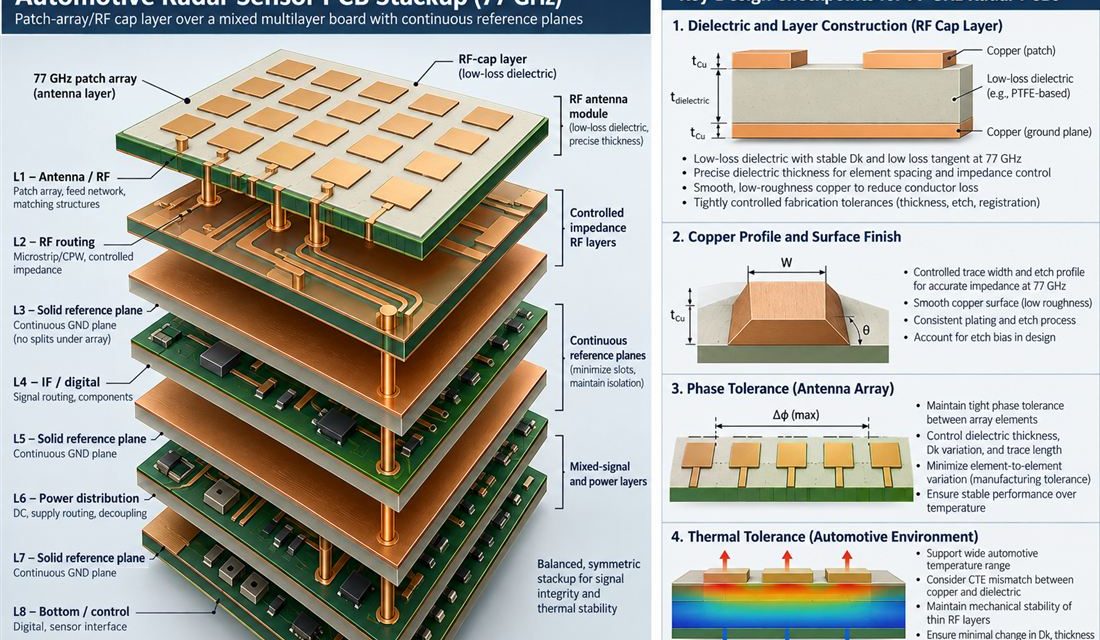
Hybrid Stackup Integration and Impedance Control of RF-35 PCBs for Automotive mmWave Radar Sensors

Engineering Context — Why RF-35 PCB Is Key to Automotive Radar Precision   As modern automotive radar systems evolve toward 76–81 GHz mmWave operation, PCB materials must ensure phase stability, low insertion loss, and precise impedance control across multiple layers.The RF-35 PCB, a Taconic PTFE glass-reinforced laminate, combines Df = 0.0018 @ 10 GHz and...