HomeTag

automotive assembly - KKPCB

Turning an ADAS Sensor PCB Prototype Into a Traceable Build

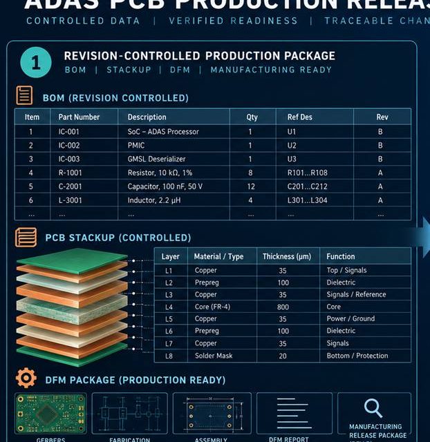
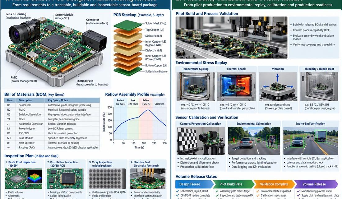
ADAS Sensor PCB — The final risk in camera, radar, and perception sensor electronics that must preserve deterministic data paths while surviving vehicle vibration, condensation, and repeated service handling is rarely a single missing trace. It is a mixed revision: a stackup updated by procurement, a connector changed by sourcing, an assembly profile copied from...
An Assembly Evidence Plan for Reliable ADAS Sensor PCB Production

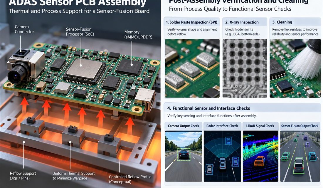
ADAS Sensor PCB — Fabrication can meet a drawing and assembly can still move the electrical result. Paste height, reflow warpage, shield force, cleaning chemistry, heat spreaders, and connector rework all act on camera, radar, and perception sensor electronics that must preserve deterministic data paths while surviving vehicle vibration, condensation, and repeated service handling. This...

Keeping Sensor Data Clean Through an ADAS Sensor PCB Transition

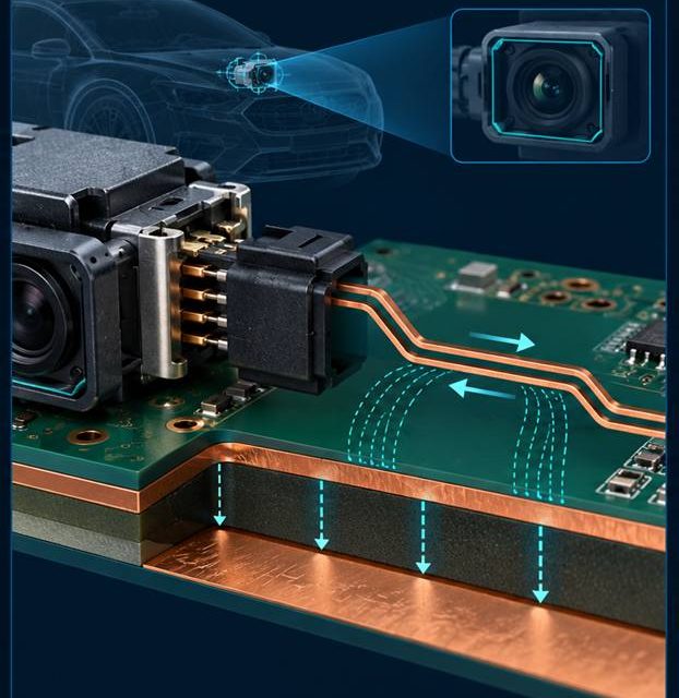
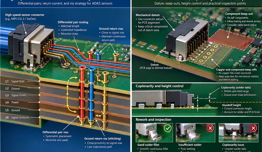
ADAS Sensor PCB — The connector, coax, antenna, sensor flex, or board edge is where a schematic becomes a three-dimensional part. In camera, radar, and perception sensor electronics that must preserve deterministic data paths while surviving vehicle vibration, condensation, and repeated service handling, that interface also has to survive mating force, housing tolerances, and service...

A Stackup Release Method for High-Speed ADAS Sensor PCB Links

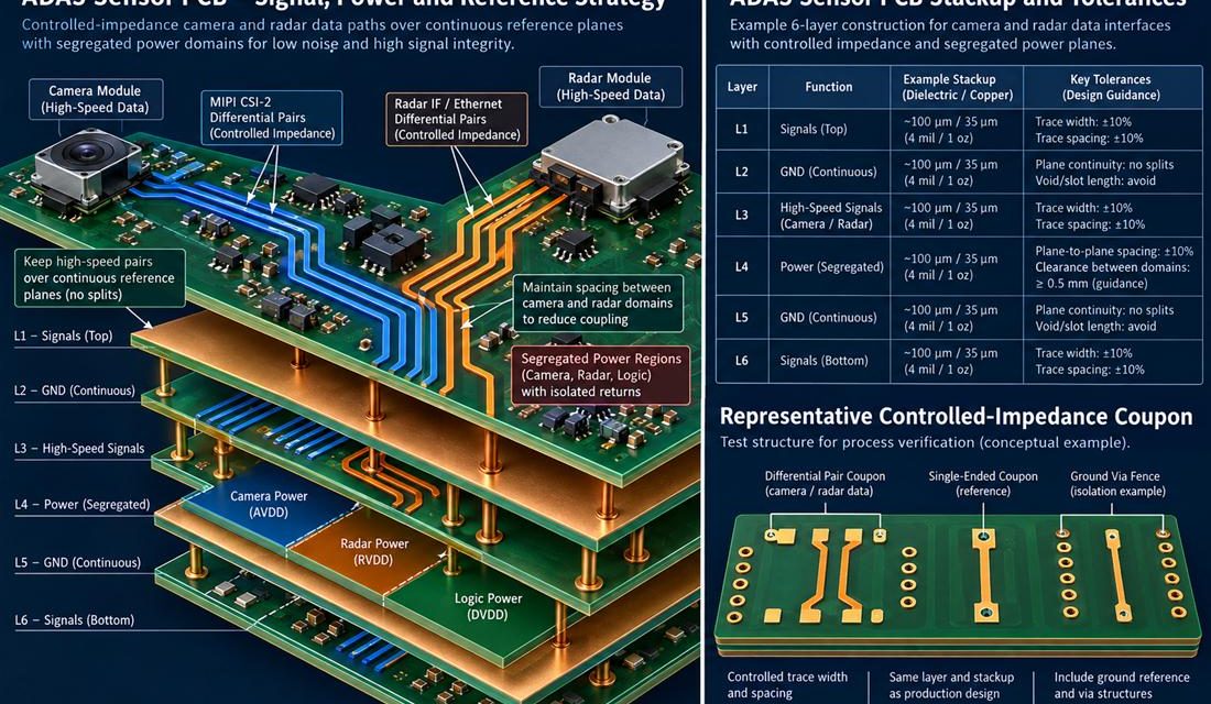
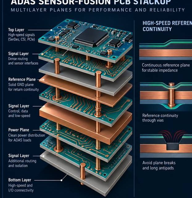
ADAS Sensor PCB — A layer list is not a stackup release. In camera, radar, and perception sensor electronics that must preserve deterministic data paths while surviving vehicle vibration, condensation, and repeated service handling, the board carries power, digital edges, RF or sensor signals, and mechanical loads at the same time. The ADAS Sensor PCB...

An Assembly Control Plan for High-Reliability ADAS PCB Production

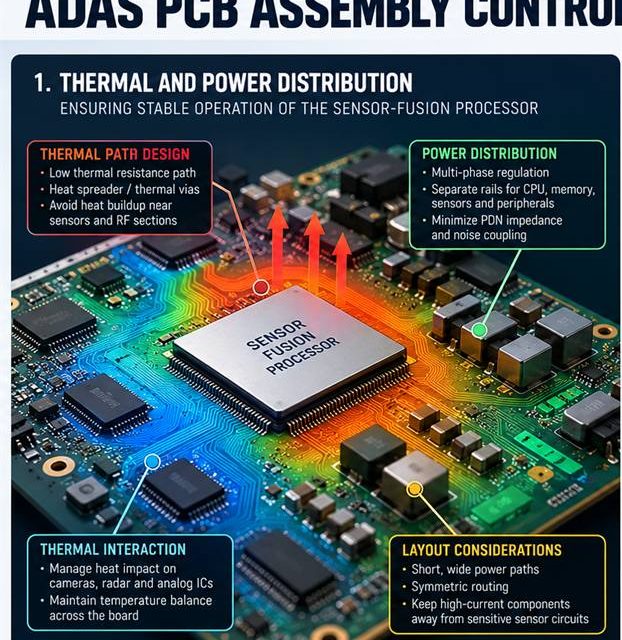
ADAS PCB assembly release begins by treating heat, solder, cleaning, and mechanical force as RF variables. An RF board can leave fabrication within drawing limits and still change during paste printing, reflow, shielding, cleaning, or mechanical assembly. That risk is amplified in camera, radar, and domain-controller electronics that must keep data paths deterministic while surviving...

Keeping High-Speed Sensor Links Quiet Through an ADAS PCB Connector Transition

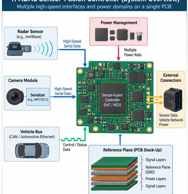
ADAS PCB launch design begins with a complete three-dimensional signal and return path. The boundary between a board and a connector, coax, antenna, or shield is where a clean schematic becomes a three-dimensional electromagnetic problem. In camera, radar, and domain-controller electronics that must keep data paths deterministic while surviving automotive assembly and service constraints, that...

Making an ADAS PCB Stackup Manufacturable Before the First Prototype

ADAS PCB stackup release begins by making every electromagnetic and manufacturing assumption visible. Stackup discussions fail when the drawing lists layer names but not the electromagnetic and manufacturing assumptions behind them. In camera, radar, and domain-controller electronics that must keep data paths deterministic while surviving automotive assembly and service constraints, the board must carry RF...

Diagnosing Intermittent Data Errors on an ADAS PCB During Vehicle Integration

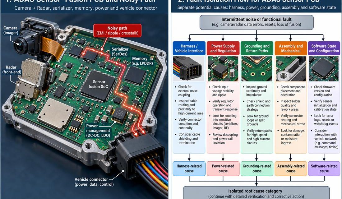
ADAS PCB fault isolation begins at the physical boundary where the symptom is reproduced. A camera, radar, and domain-controller electronics that must keep data paths deterministic while surviving automotive assembly and service constraints can pass a schematic review and still fail in the chamber, the enclosure, or the vehicle. The failure often appears as a...