Blog

Explore the KKPCB Blog for the latest PCB manufacturing and assembly news, industry insights, expert tips, and technology trends, helping you stay informed and optimize your electronics projects.
Designing the Connector Launch of an Automotive High Frequency PCB

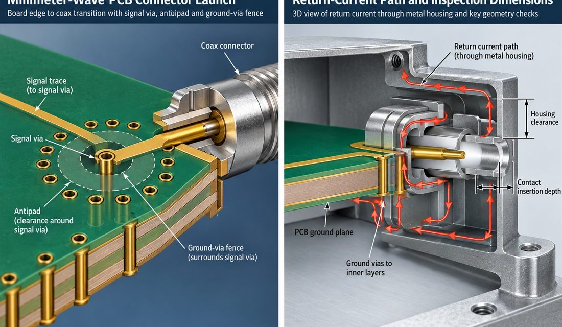
Automotive High Frequency PCB — The connector, coax, antenna, sensor flex, or board edge is where a schematic becomes a three-dimensional part. In high-frequency automotive radar and connectivity boards where fast edges, 76–81 GHz channels, and a constrained metal housing share the same release, that interface also has to survive mating force, housing tolerances, and...
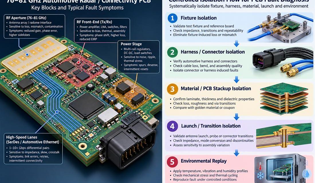
Finding the Physical Cause of Drift in an Automotive High Frequency PCB

Automotive High Frequency PCB — A vehicle program can report an intermittent reset, a communication dropout, a radar sensitivity loss, or a calibration value that moves only after the enclosure is closed. That symptom is not yet a PCB diagnosis. On a Automotive High Frequency PCB, the board shares its boundary with a harness, connector,...

Protecting Power and Signal Integrity During Automotive Electronics PCB Assembly

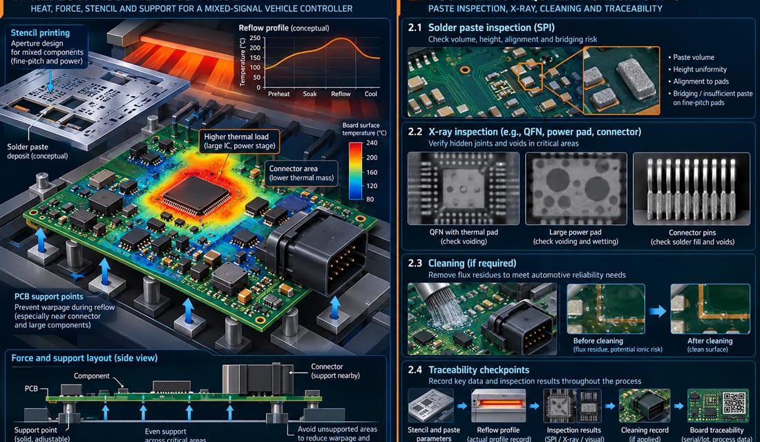
Automotive Electronics PCB — Fabrication can meet a drawing and assembly can still move the electrical result. Paste height, reflow warpage, shield force, cleaning chemistry, heat spreaders, and connector rework all act on vehicle electronic control units that combine CAN-FD, automotive Ethernet, sensor power, memory, and actuator drivers in a vibration and temperature exposed enclosure....

Connector and Via Transitions That Keep an Automotive Electronics PCB Predictable

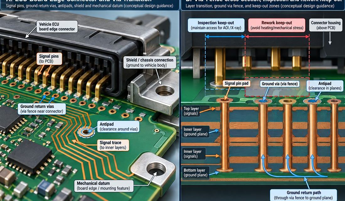
Automotive Electronics PCB — The connector, coax, antenna, sensor flex, or board edge is where a schematic becomes a three-dimensional part. In vehicle electronic control units that combine CAN-FD, automotive Ethernet, sensor power, memory, and actuator drivers in a vibration and temperature exposed enclosure, that interface also has to survive mating force, housing tolerances, and...
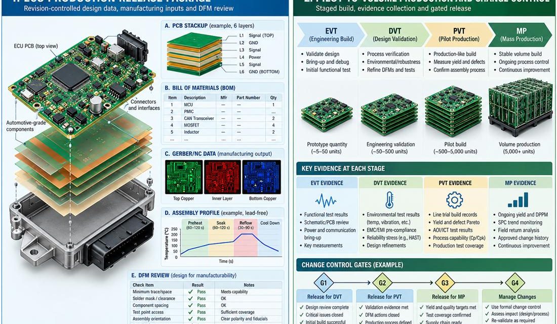
Building an Automotive Electronics PCB Stackup That Survives Mixed-Signal Reality

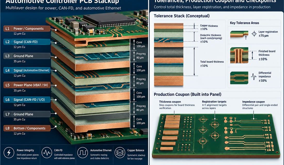
Automotive Electronics PCB — A layer list is not a stackup release. In vehicle electronic control units that combine CAN-FD, automotive Ethernet, sensor power, memory, and actuator drivers in a vibration and temperature exposed enclosure, the board carries power, digital edges, RF or sensor signals, and mechanical loads at the same time. The Automotive Electronics...

When an Automotive Electronics PCB Fails Only in the Vehicle: A Root-Cause Workflow

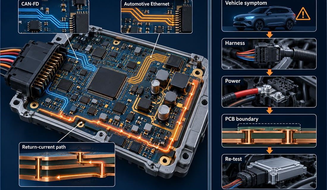
Automotive Electronics PCB — A vehicle program can report an intermittent reset, a communication dropout, a radar sensitivity loss, or a calibration value that moves only after the enclosure is closed. That symptom is not yet a PCB diagnosis. On a Automotive Electronics PCB, the board shares its boundary with a harness, connector, shield, heat...

An Assembly Control Plan for High-Reliability ADAS PCB Production

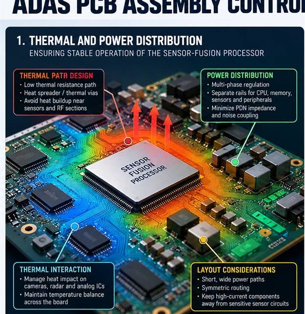
ADAS PCB assembly release begins by treating heat, solder, cleaning, and mechanical force as RF variables. An RF board can leave fabrication within drawing limits and still change during paste printing, reflow, shielding, cleaning, or mechanical assembly. That risk is amplified in camera, radar, and domain-controller electronics that must keep data paths deterministic while surviving...