low-loss PCB - KKPCB
 
HomeTag

low-loss PCB - KKPCB

Multilayer HF PCBs: Optimized Solutions for High-Frequency, High-Density Designs

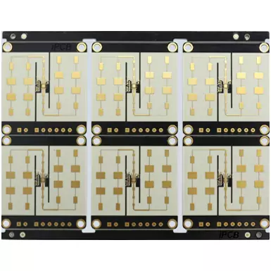
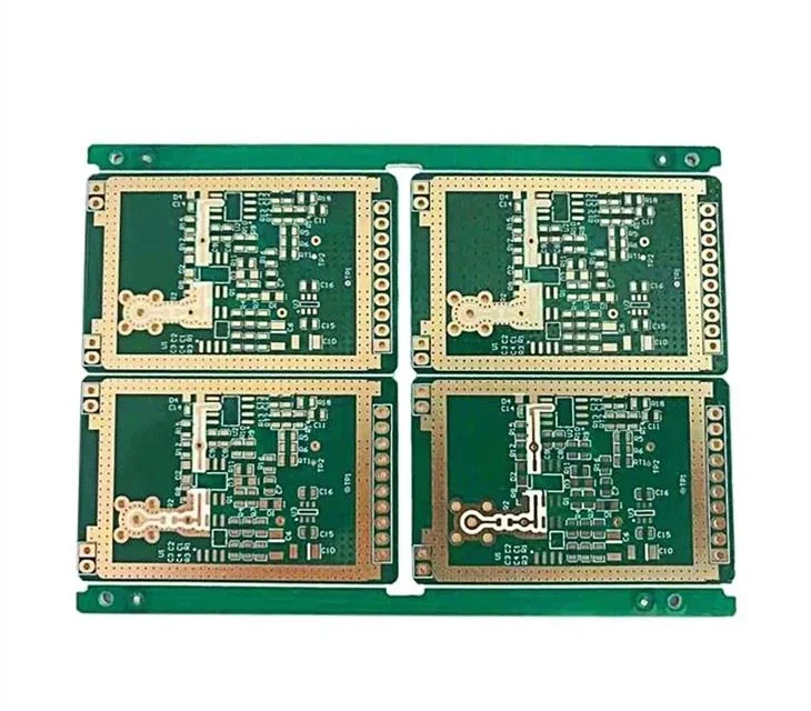
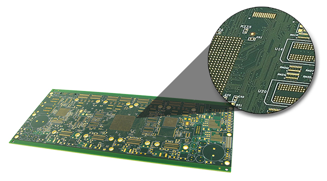
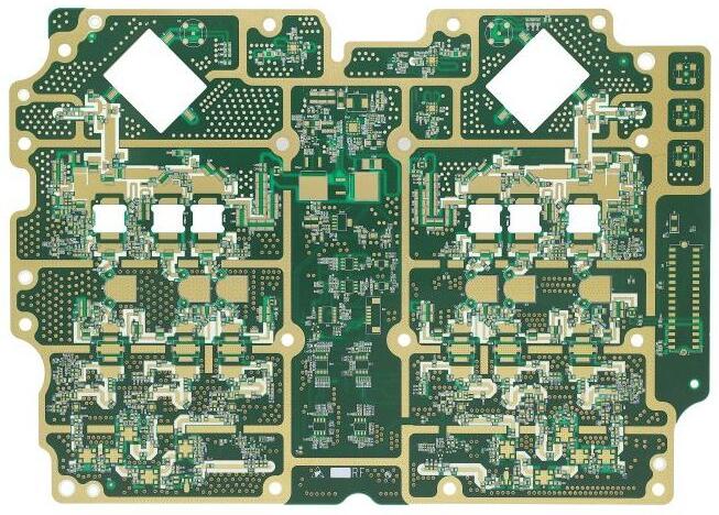
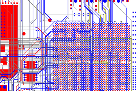
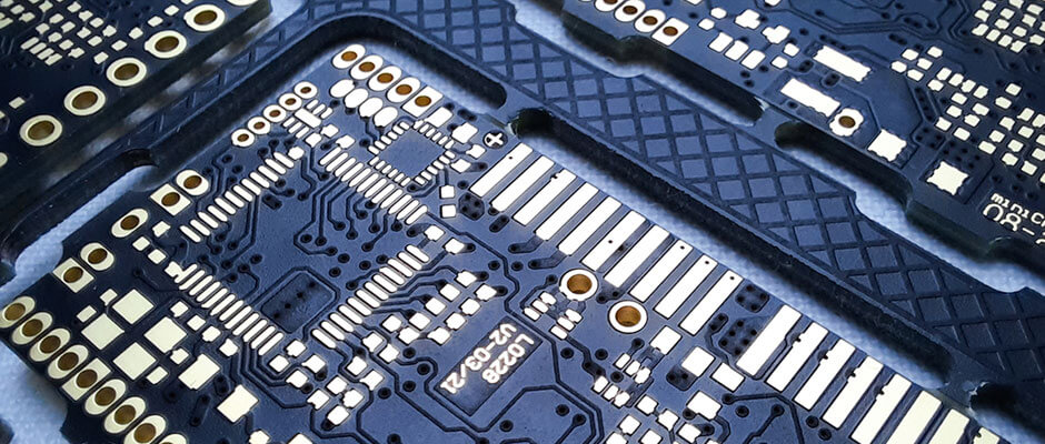
A Multilayer HF PCB is a printed circuit board engineered for high-frequency signal transmission across multiple layers. Unlike standard multilayer boards, HF (high-frequency) PCBs are optimized for low dielectric loss, controlled impedance, and minimal crosstalk, enabling high-speed signal integrity in demanding applications. Multilayer HF PCBs are commonly used in: RF and microwave modules Wireless communication...

5G Router PCBs: Engineering High-Speed Connectivity for Next-Generation Networks

A 5G Router PCB is a high-performance printed circuit board designed to enable ultra-fast data transmission, low latency, and stable wireless connectivity in modern communication systems. Unlike traditional router boards, 5G routers must handle multi-gigabit data rates, high-frequency RF signals, and complex multi-antenna (MIMO) architectures. Typical 5G router PCB systems integrate: RF front-end modules (power...

RF-35 PCBs: Cost-Effective Low-Loss Solutions for RF Applications

An RF-35 PCB is a printed circuit board built using Taconic RF-35 laminate, a ceramic-filled PTFE-based material designed for high-frequency applications. With a dielectric constant of approximately 3.5 and a low dissipation factor, RF-35 provides a balance between signal performance, thermal stability, and manufacturability. Compared to standard FR-4, RF-35 significantly reduces signal loss at high...

RO4350B PCBs: Reliable High-Frequency Performance with Low-Loss Materials

An RO4350B PCB is a printed circuit board built using Rogers RO4350B laminate, a widely adopted high-frequency material known for its low dielectric loss, stable dielectric constant (Dk ≈ 3.48), and excellent thermal reliability. Unlike traditional PTFE-based materials, RO4350B is a hydrocarbon ceramic laminate, which combines high-frequency performance with easier manufacturability similar to standard FR-4...

RF Test PCBs: Precision Solutions for High-Frequency Component Validation

An RF Test PCB is a printed circuit board engineered to support high-frequency testing, characterization, and validation of RF and microwave components. Unlike standard PCBs, RF test boards are optimized for signal integrity, controlled impedance, and minimal insertion loss, ensuring that measurements accurately reflect the performance of devices under test (DUT). RF test PCBs are...

Rogers PCBs: High-Performance Solutions for RF and Microwave Applications

A Rogers PCB is a printed circuit board made from Rogers high-frequency laminates, engineered to provide stable dielectric constants (Dk), low dissipation factors (Df), and superior thermal performance. These features make Rogers PCBs ideal for RF, microwave, and high-speed digital circuits where signal integrity is critical. Rogers PCBs are widely used in: Wireless communication systems...

RF Trace PCBs: Designing for High-Frequency Signal Performance

An RF Trace PCB is a printed circuit board optimized for radio frequency (RF) and microwave signals, typically operating from hundreds of MHz to several GHz. Unlike standard PCBs, RF trace boards must maintain signal integrity, controlled impedance, and minimal insertion loss across the board. RF trace PCBs are widely used in: Wireless communication systems...

Fine Line PCBs: Precision Design for High-Density and High-Speed Electronics

A Fine Line PCB is a printed circuit board that features extremely narrow traces and spacing, typically in the range of 2–4 mils (50–100 μm), allowing engineers to fit more functionality into a smaller board area. Fine line technology is critical for high-density, high-speed digital, RF, and precision analog circuits, where both space optimization and...

High-Speed Logic PCBs: Designing for Fast, Reliable Digital Circuits

A High-Speed Logic PCB is a printed circuit board designed to carry digital signals at high frequencies, often in the range of hundreds of MHz to several GHz. Unlike standard PCBs, high-speed logic boards require special attention to signal integrity, timing accuracy, and electromagnetic compatibility. These PCBs are commonly used in: Multi-gigabit computing systems FPGA...

Signal Integrity PCBs: Maintaining High-Speed Signal Quality in Modern Electronics

What is a Signal Integrity PCB? A Signal Integrity PCB is a printed circuit board optimized for accurate transmission of high-speed signals, minimizing signal degradation, reflections, and timing errors. As electronic systems reach multi-gigabit speeds, standard PCBs may suffer from signal attenuation, crosstalk, or EMI, which compromises performance. SI PCBs are critical in applications such...