Controlled Impedance PCB - KKPCB
 
HomeTag

Controlled Impedance PCB - KKPCB

Taconic PCB: High-Frequency Materials for Reliable RF and Microwave Designs

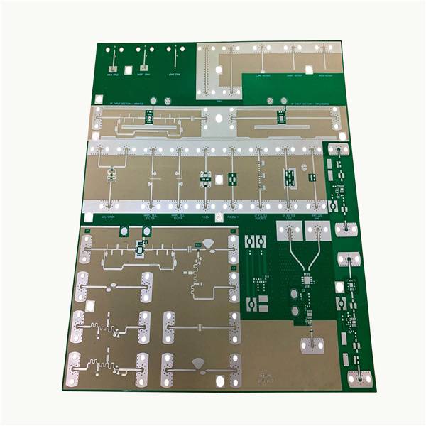
What Is a Taconic PCB? A Taconic PCB is a high-performance RF PCB manufactured using Taconic materials, which are engineered for low loss, stable dielectric properties, and reliable high-frequency performance. Taconic PCB materials are widely used in RF, microwave, and high-speed digital applications, where signal integrity is critical. Common Taconic material families used in Taconic...

PTFE PCB: Ultra-Low Loss Materials for High-Frequency RF Applications

What Is a PTFE PCB? A PTFE PCB is a high-performance RF PCB built using PTFE material (Polytetrafluoroethylene), engineered for ultra-low signal loss and stable high-frequency performance. PTFE PCB materials are widely used in microwave, RF, and mmWave PCB designs, where traditional materials cannot maintain signal integrity. Key characteristics of PTFE PCB materials include: Very...

Rogers PCB: High-Frequency Performance, Materials, and Design Considerations

What Is a Rogers PCB? A Rogers PCB is a high-performance RF PCB manufactured using Rogers materials, which are engineered for low loss, stable dielectric properties, and high-frequency performance. Unlike standard FR-4 boards, Rogers PCB materials are designed to maintain consistent electrical behavior at GHz and mmWave frequencies, making them ideal for RF and microwave...

RF Trace PCB Design: Optimizing High-Frequency Signal Paths for Maximum Performance

What Is an RF Trace PCB? An RF Trace PCB is a specialized RF PCB where signal routing is designed as controlled transmission lines to carry high-frequency signals with minimal loss and distortion. In RF Trace PCB design, traces are no longer simple connections—they function as engineered RF signal paths, where geometry, materials, and layout...

RF IC Test PCBs: Precision Platforms for High-Frequency Device Validation

Why RF IC Testing Is Fundamentally Different Testing RF integrated circuits is significantly more demanding than standard digital testing. An RF IC Test PCB must handle GHz-level signals, where even small discontinuities can distort measurement results. Unlike digital systems, RF testing is highly sensitive to: Signal loss and phase shift Impedance discontinuities Parasitic effects from...

Low Loss PCBs: Minimizing Signal Attenuation in High-Speed and RF Designs

Why Loss Matters in Modern PCB Design As data rates and frequencies continue to increase, signal loss becomes one of the primary limiting factors in PCB performance. In high-speed digital systems and RF designs, excessive loss leads to: Signal degradation and eye diagram closure Reduced transmission distance Increased bit error rates (BER) Lower system reliability...

Duroid 6002 PCBs: Stable Dielectric Performance for Precision RF Designs

Why Duroid 6002? In RF and microwave PCB design, consistency is often more critical than absolute performance. Duroid 6002 PCB, based on Rogers RT/duroid 6002 laminate, is widely chosen for its exceptionally stable dielectric constant and predictable electrical behavior. With a dielectric constant (Dk) of approximately 2.94 and a low dissipation factor, this material offers...

TLY-5 PCBs: High-Frequency, Low-Loss Solutions for Advanced Electronics

A TLY-5 PCB is a printed circuit board constructed using Taconic TLY-5 laminate, a ceramic-filled PTFE material optimized for high-frequency applications. TLY-5 combines low dielectric loss, stable dielectric constant, and thermal reliability, making it suitable for RF, microwave, and high-speed digital circuits. TLY-5 PCBs are widely used in: Wireless communication modules High-speed networking equipment RF...

Blind Via PCBs: High-Density Interconnections for Advanced Electronics

A Blind Via PCB is a multilayer printed circuit board that uses vias connecting an outer layer to one or more inner layers without extending through the entire board. Unlike through-hole vias, blind vias do not penetrate all layers, allowing for high-density routing, reduced board size, and improved signal integrity. Blind via technology is critical...

Multilayer HF PCBs: Optimized Solutions for High-Frequency, High-Density Designs

A Multilayer HF PCB is a printed circuit board engineered for high-frequency signal transmission across multiple layers. Unlike standard multilayer boards, HF (high-frequency) PCBs are optimized for low dielectric loss, controlled impedance, and minimal crosstalk, enabling high-speed signal integrity in demanding applications. Multilayer HF PCBs are commonly used in: RF and microwave modules Wireless communication...