Sensing technology provides companies with an opportunity to enhance functionality in existing products. In the Internet of Things (IoT) space, sensor shipments are projected to increase by almost 20 billion units from 2020 to 2024, with radar sensing growing at a compound annual growth rate of approximately 30%.
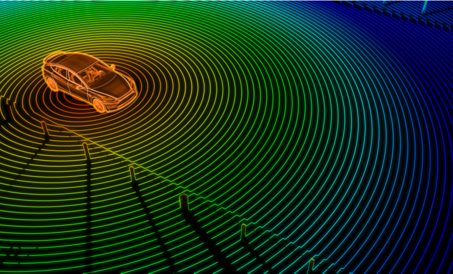
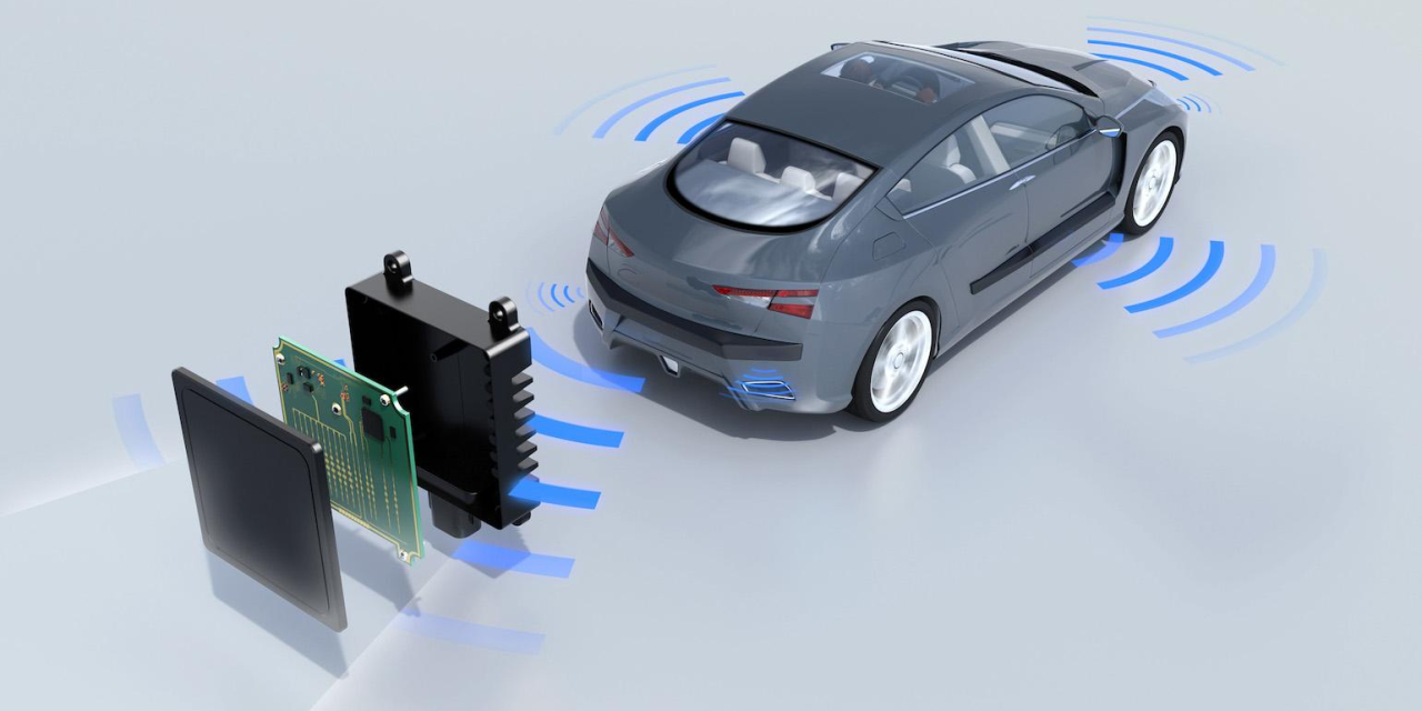
Interest in TI millimeter-wave (mmWave) radar is rising due to its many advantages, including the ability to operate in challenging environments, avoid privacy concerns, and provide high-resolution range, velocity, and angle information.
This article provides insights on optimizing costs associated with mmWave radar sensing solutions, shares real-world examples of new product ideas, and explores actual board design strategies to accelerate development.
Cost Reduction Enables New Opportunities
For systems already incorporating mmWave radar, reducing costs can create new price points to fill gaps in the product portfolio or provide a more accessible entry point for customers. Lower-cost solutions can justify adding sensing capabilities, delivering new functionality, convenience, and marketable appeal.
For example, in building automation, a supplier of automatic doors for retail stores can offer a more affordable automatic door to attract new customers and encourage existing customers to adopt additional features. A lower-cost mmWave radar solution can enable doors to sense directionality as well as presence, reducing energy costs for heating and cooling while minimizing mechanical wear.
When reducing costs, trade-offs must be carefully considered to ensure overall product performance is not compromised.
Three Key Areas Affecting Cost
The main contributors to the cost of a typical mmWave radar board are:
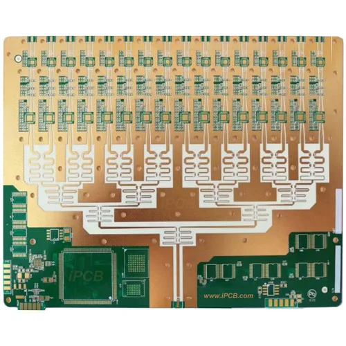
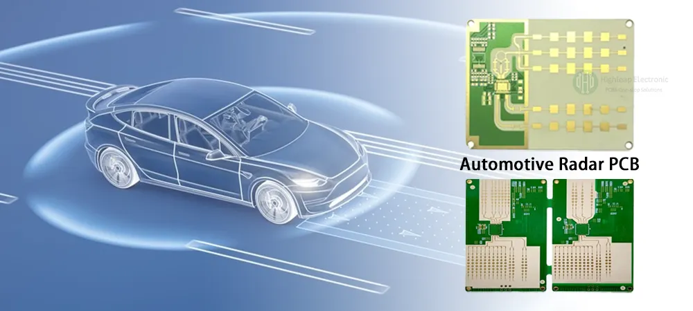
Printed Circuit Board (PCB) Design
PCB Substrate Materials and Manufacturing
Electronic Bill of Materials (eBOM)
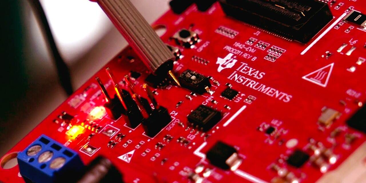
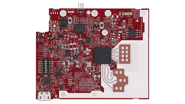
Below, we explore each area in the context of developing an mmWave radar board based on TI’s IWR6843ABGABL sensor.
Simplifying PCB Design
From a PCB design perspective, reducing complexity and avoiding high-density interconnects can significantly lower manufacturing costs. Some effective strategies include:
Replacing microvias with through vias
Avoiding vias on pads
These adjustments may slightly increase the overall board size but can lead to up to 40% cost savings, with minimal impact on board footprint.
Choosing Cost-Effective PCB Materials
While many teams may expect to use specialized Rogers laminates for radar boards, empirical testing at TI shows that using Isola FR408HR for the antenna layer can achieve acceptable performance at a lower cost.
Compared to Rogers RO4835, FR408HR offers approximately 30% savings in material costs.
FR4/FR408HR laminates are more familiar to PCB manufacturers and more readily available, further reducing fabrication costs.
Though using FR4 may slightly reduce maximum radar range (approximately 60% of the Rogers board due to ~8 dB loss), performance can still meet the requirements of typical mmWave radar systems. Range can be compensated by increasing the number of chirps and coherently combining signals, though this involves trade-offs in power consumption, on-chip memory, and processing requirements.
Reducing Electronic Bill of Materials (eBOM)
The final cost component is the BOM. To optimize cost for non-safety-critical applications, discrete DC-to-DC converters are a cost-effective choice for implementing the power subsystem of the IWR6843AQGABL radar sensor board.
For example, the IWR6843LEVM design uses the following fixed-output DC-to-DC devices:
TPS628502HQDRLRQ1
TPS6285020MQDRLRQ1
TPS6285018AQDRLRQ1
TPS628503QDRLRQ1
Using these components provides flexibility in design, inventory management, and a reduction in overall system costs. In the TI example, combined cost and area savings of approximately 10% were achieved in the supporting subsystem.
Conclusion
By optimizing PCB design, materials, and eBOM, companies can reduce costs while opening up new product opportunities and expanding existing product offerings. Applicable markets include:
Building automation (e.g., automated doors, lighting systems)
Factory automation and robotics (e.g., lawnmowers, wall-mounted AC units)
The IWR6843LEVM evaluation module demonstrates these savings in a practical mmWave radar application.
Through careful consideration of design, material selection, and BOM, developers can create cost-effective mmWave radar boards without compromising performance, enabling innovative IoT solutions across multiple industries.