EMI Control PCB - KKPCB
 
HomeTag

EMI Control PCB - KKPCB

High Frequency Signal PCB: Low-Loss Routing and Controlled Impedance for Stable RF Performance

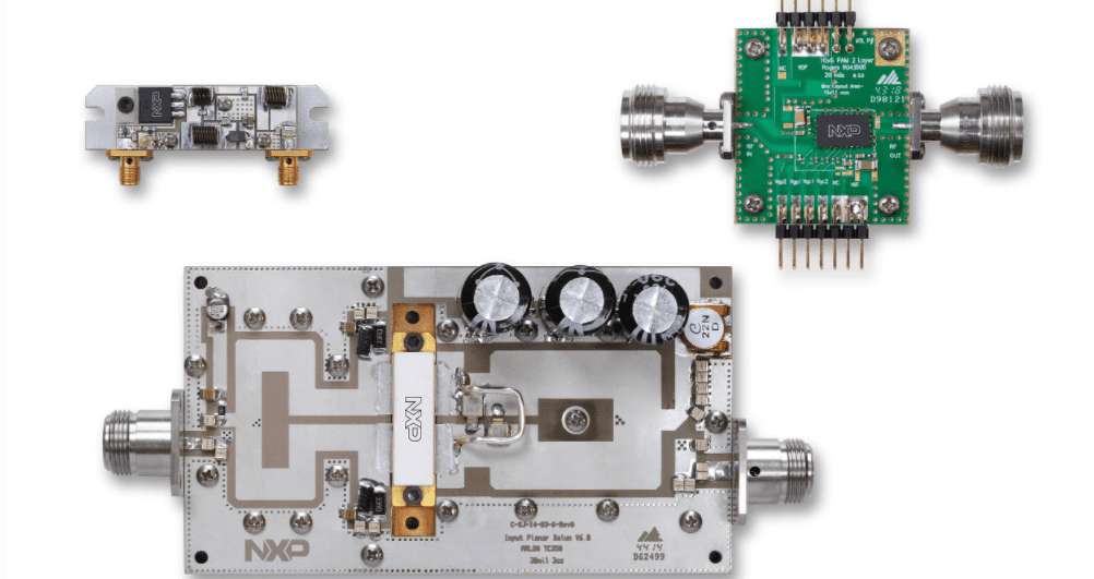
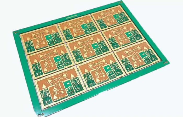
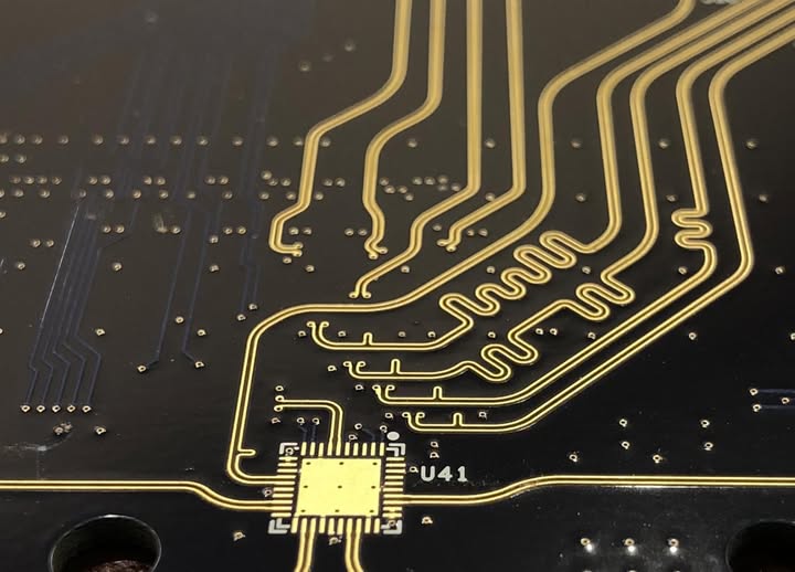
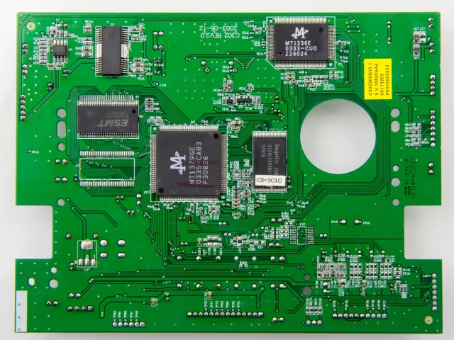
A High Frequency Signal PCB is a specialized printed circuit board engineered to transmit high frequency signals with low loss, stable impedance, and excellent signal integrity. As wireless communication and high-speed electronics continue to advance, high frequency PCB performance becomes a key factor in system stability, compliance, and overall product reliability. Unlike standard PCBs used...

RF Trace PCB: Precision RF Routing for High-Frequency and Low-Loss Signal Transmission

An RF Trace PCB is a specialized printed circuit board designed for RF signal transmission and high-frequency applications, where signal loss, impedance stability, and EMI control are critical. As wireless technologies such as 5G, WiFi, GPS, IoT, and radar systems continue to grow, RF PCB performance requirements become stricter than ever. Unlike ordinary digital traces,...

High Frequency Signal PCB: Optimized Design for Low-Loss and Stable High-Speed Signals

What Is a High Frequency Signal PCB? A High Frequency Signal PCB is a printed circuit board designed to transmit high-frequency electrical signals—typically in the MHz to GHz range—while maintaining signal integrity, minimizing loss, and reducing EMI. These PCBs are critical in applications such as RF communication, microwave devices, 5G modules, radar systems, high-speed networking,...

Differential Pair PCB: Controlled Impedance Routing for High-Speed and Low-Noise Signal Transmission

What Is a Differential Pair PCB? A Differential Pair PCB is a printed circuit board designed with differential signal pairs to transmit high-speed data with improved noise immunity and stable signal quality. A differential pair consists of two matched traces carrying equal and opposite signals, allowing the receiver to detect the voltage difference between them....

High Speed Logic PCB: Controlled Impedance and Signal Integrity for Fast Digital Systems

What Is a High Speed Logic PCB? A High Speed Logic PCB is a printed circuit board designed for high-speed digital logic signals that require stable timing, clean waveforms, and reliable data transmission. Unlike standard PCBs, a High Speed Logic PCB must handle fast edge rates, high-frequency harmonics, and strict signal integrity requirements for interfaces...

Power Integrity PCB: Ensuring Stable Voltage and Reliable High-Speed Electronics

What Is a Power Integrity PCB? A Power Integrity PCB is a printed circuit board engineered to deliver stable voltage, low-noise power, and reliable current distribution to high-speed ICs such as CPUs, GPUs, FPGAs, ASICs, and high-density memory devices. In modern electronics, core voltages are getting lower while current demand is increasing, which makes power...

Signal Integrity PCB: Designing for Clean Signals, Low Noise, and High-Speed Performance

What Is a Signal Integrity PCB? A Signal Integrity PCB is a printed circuit board specifically designed and manufactured to ensure high-speed signals remain stable, clean, and reliable from transmitter to receiver. In modern electronics, as data rates increase and edge rates become faster, signal integrity (SI) becomes one of the most critical performance factors...

Optimize Low-Loss Signal Chains and EMI Control Using RF Transceiver PCB Designs for High-Frequency Communication Systems

High-frequency communication systems—from 5G NR radios and phased-array front ends to satellite downlink modules and wideband radar—rely on precisely engineered RF Transceiver PCB architectures to maintain low-loss signal chains, stable phase performance, and strong EMI suppression. As operating frequencies rise into sub-6 GHz, C-band, Ku-band, Ka-band and even mmWave ranges, the electrical behavior of the...