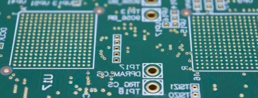
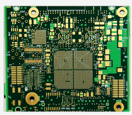
PCB Design - KKPCB
 
HomeCategory

PCB Design - KKPCB

SMT vs THT PCB Assembly Process: Difference Analysis

Surface Mount Technology (SMT) and Through-Hole Technology (THT) are two key PCB assembly methods widely used in electronics manufacturing. Both technologies have their own distinct advantages, applications, and processes. In this article, we will explore the differences between SMT and THT, examining the assembly steps, key features, and when each technology is ideal for use. What is...

PCB Substrate and Core Materials: A Comprehensive Guide

The Printed Circuit Board (PCB) is a fundamental component in all modern electronics, providing the platform for the electronic components and circuits. The performance, durability, and overall quality of a PCB are heavily influenced by the materials used for its substrate and core. This comprehensive guide explores the different types of PCB substrate and core materials, their properties, applications, and why they are...

PCB Substrate Materials: Understanding the Types of PCB Materials

PCB (Printed Circuit Board) substrate materials are the backbone of a PCB assembly, providing the necessary foundation for copper tracks and electronic components. The choice of PCB material plays a critical role in determining the performance, durability, and overall reliability of the PCB. These materials can be resin-based, fiberglass-based, epoxy-glass, metal-based, or flame-retardant, and they are...

PCB for SMT (Surface Mount Technology): Choosing the Right PCB for SMD Components

What is a PCB? A Printed Circuit Board (PCB) is a vital component in almost every electronic product. It serves as the foundation for connecting electronic components through conductive paths (traces), typically made of copper. The traces facilitate the flow of electrical current, enabling electronic devices to function. A PCB can be made of various materials, such...

Advantages and applications of single-sided PCB

What is a Single-Sided PCB? A Single-Sided PCB (also known as a Single-Layer PCB or One-Layer PCB) is the simplest and most cost-effective type of printed circuit board. As the name suggests, it has a single conductive layer (usually copper) on one side of the substrate, with the electronic components mounted on the opposite side. Unlike double-sided PCBs, which feature conductive layers on both sides, single-sided...

Multilayer PCB Manufacturing Process, Advantages and Applications

What is a Multilayer PCB? A Multilayer PCB (Printed Circuit Board) is a type of PCB with more than two conductive layers. Unlike a double-sided PCB, which has two copper layers (top and bottom), a multilayer PCB consists of three or more layers of copper, interconnected by copper-plated vias. The number of layers can range from 3 layers to 40 layers or more, depending on...

PCB Design and Fabrication for Millimeter-Wave Circuits (Part 1)

Key Points of Millimeter-Wave Applications—Phase Accuracy Affected by Multiple Variables From anti-collision radar systems used in autonomous vehicles to the fifth-generation (5G) high data rate New Radio (NR) networks, the application of millimeter-wave (mmWave) circuits is growing rapidly. Many applications are pushing the operating frequency bands to higher frequencies (such as >24GHz). However, for circuits with shorter...

Microvia Reliability in High-Density Designs

As high-density interconnect (HDI) designs with larger layer counts become more prevalent, the use of microvias is increasing. In builds with 3+N+3 or larger configurations, sequential lamination now often relies on skipped vias, staggered microvias, and stacked microvias. However, one of the key challenges is that microvias are more susceptible to failure than plated through-holes. The small...

Copper Current Density in PCB Design

Copper current density refers to the amount of continuous current flowing through a copper trace on a PCB. According to Joule or Ohmic heating principles (represented as VI or I²R), any conductive material generates heat, leading to a gradual temperature rise in both the conductor and its surroundings. Managing copper current density is critical to...

PCB Layout Planning – Packages and Routing

PCB layout planning is a critical phase in the design process, enabling engineers to save time and ensure a structured approach to package management, component placement, and routing. Proper planning ensures that the design meets electrical, spacing, and physical requirements before moving to the actual layout stage. This article explores key aspects of PCB layout planning, focusing on footprint management, routing strategies,...