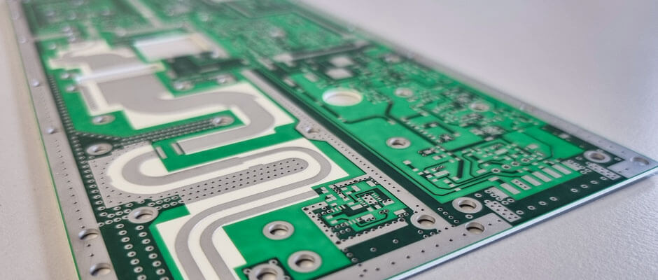
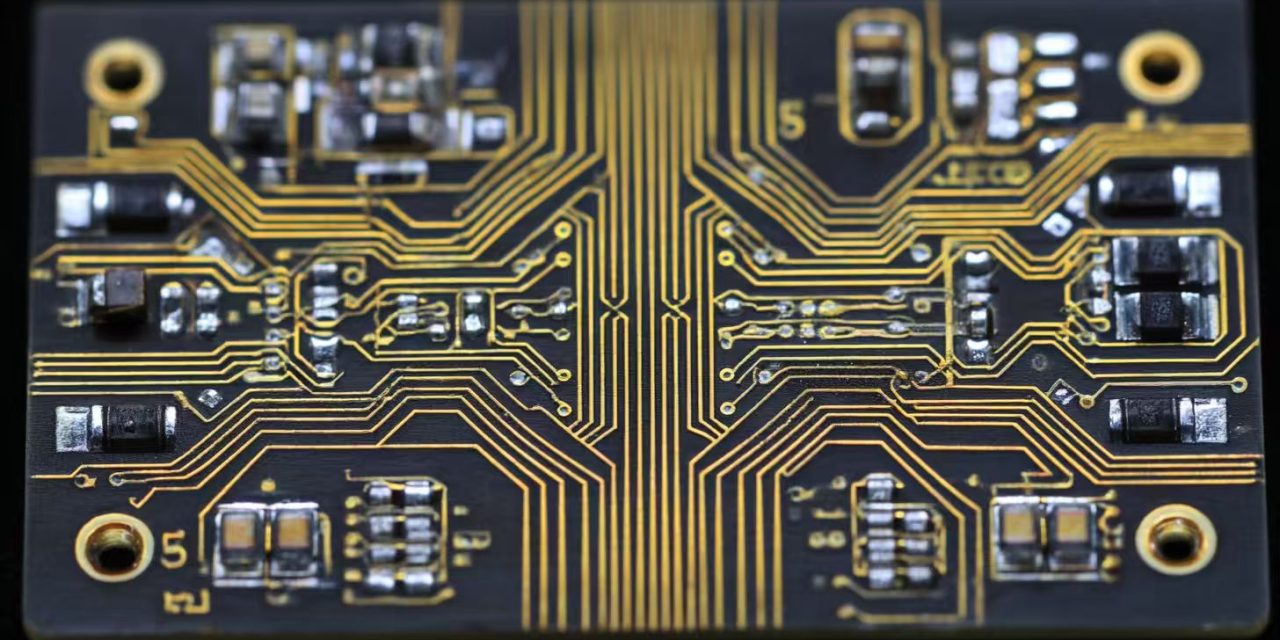
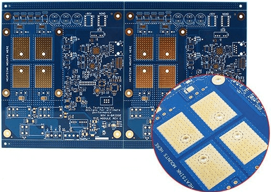
What Is RF-35 PCB? An RF-35 PCB is a high frequency printed circuit board fabricated using Taconic RF-35 laminate material. It is designed for RF and microwave applications that require low signal loss, stable dielectric performance, and consistent impedance control. RF-35 is a glass-reinforced PTFE-based laminate filled with ceramic materials to enhance mechanical strength and...
HomeCategory
PCB Design Services | Professional PCB Layout & Design - KKPCB
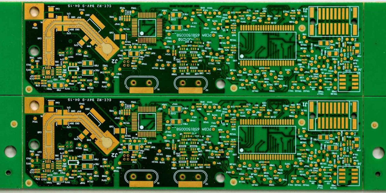
What Is RO4350B PCB? A RO4350B PCB is a high frequency printed circuit board fabricated using Rogers RO4350B laminate material. It is widely used in RF, microwave, and high speed digital applications due to its low dielectric loss, stable dielectric constant, and excellent thermal performance. Compared with standard FR-4 material, RO4350B provides significantly improved signal...
What Is a Logic Test PCB? A Logic Test PCB is a specialized printed circuit board designed for testing and validating digital and logic integrated circuits (ICs). These boards are used in semiconductor development, production testing, and automated test equipment (ATE) systems to verify functionality, timing performance, and signal integrity of logic devices. Logic Test...
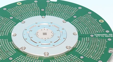
What Is a Burn-in PCB? A Burn-in PCB is a specialized printed circuit board designed for semiconductor burn-in testing. It is used to apply electrical and thermal stress to integrated circuits (ICs) over an extended period to identify early-life failures and ensure long-term reliability. Burn-in testing is a critical quality control process in semiconductor manufacturing,...
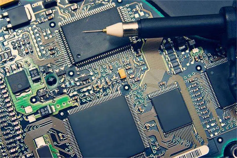
RF Test PCB – Ensuring Accurate High Frequency Testing Performance An RF Test PCB is a specialized printed circuit board designed to evaluate, validate, and characterize radio frequency (RF) components, modules, and integrated circuits. These boards are used in laboratory testing, production testing, and automated test equipment (ATE) systems to ensure RF devices meet performance...
What Is a Taconic PCB? A Taconic PCB is a printed circuit board manufactured using high-performance laminates produced by Taconic Advanced Dielectric Division. These materials are widely recognized for their excellent high-frequency electrical properties, low dielectric loss, and stable performance in demanding RF and microwave applications. Taconic materials are commonly used in: RF PCB Microwave...
Who Is an ATE PCB Supplier? An ATE PCB Supplier is a professional manufacturer and solutions provider of printed circuit boards specifically designed for Automated Test Equipment (ATE) used in semiconductor testing. These suppliers deliver PCBs that serve as the electrical interface between ATE systems and devices under test (DUTs), enabling accurate functional, parametric, and...
What Are Hybrid PCB Materials? Hybrid PCB materials refer to multilayer PCB constructions that combine two or more different laminate materials within the same stack-up. Instead of using a single material throughout the board, hybrid PCB designs integrate materials such as: Standard FR-4 High TG materials Low loss laminates High frequency laminates (Rogers, PTFE, etc.)...
What Are High TG Materials? High TG materials refer to PCB laminate materials with a high glass transition temperature (Tg), typically above 170°C and often reaching 180°C–200°C or higher. The Tg value indicates the temperature at which the PCB material transitions from a rigid glass-like state to a softer rubber-like state. Using high TG materials...
What Are Low Loss Materials? Low loss materials are specialized PCB laminate materials designed to minimize signal attenuation in high-speed and high-frequency circuits. Compared to standard FR-4 materials, low loss materials provide: Lower dissipation factor (Low Df) Stable dielectric constant (Dk) Reduced insertion loss Improved signal integrity Better high-frequency performance Low loss materials are essential...

