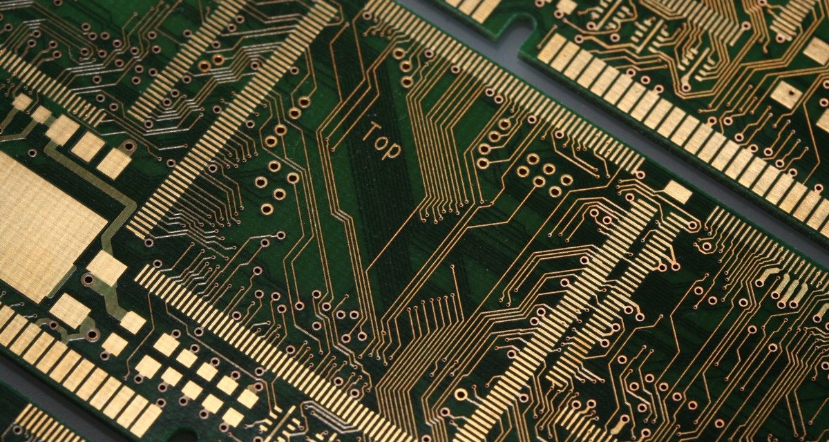
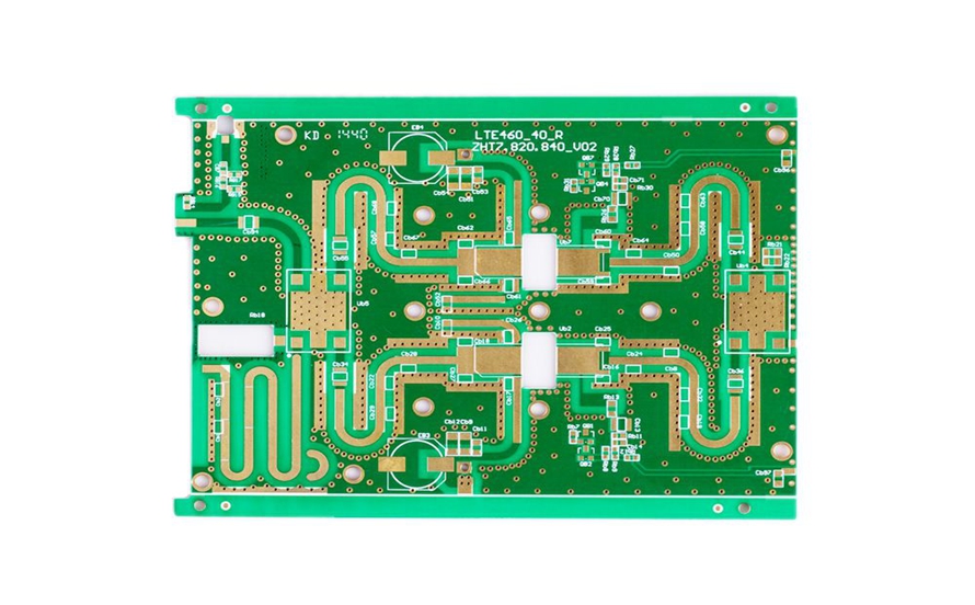
kkpcb04 - KKPCB - Page 13 of 65
 
HomeAuthor

kkpcb04 - KKPCB - Page 13 of 65

Differential Pair PCB: Controlled Impedance Routing for High-Speed, Low-Noise Signal Integrity

A Differential Pair PCB is a printed circuit board designed to route signals in pairs of two complementary traces, where one carries the positive signal and the other carries the negative signal. Instead of relying on a single-ended reference to ground, differential signaling transmits information through the voltage difference between the two traces, making it...

Megtron 6 PCB: Ultra-Low Loss High-Speed Material for High Reliability and Next-Gen Data Rates

A Megtron 6 PCB is a high-performance ultra low loss PCB built with Panasonic Megtron 6 laminate, designed for demanding high-speed digital and high-frequency signal applications. As next-generation electronics continue to push data rates higher—such as advanced SerDes links, high-speed networking, and data center backplanes—standard FR-4 and even some low-loss materials may struggle to meet...

RO4003C PCB: High-Frequency Rogers Material for Low Loss and Stable Impedance Control

What Is an RO4003C PCB? An RO4003C PCB is a high-frequency printed circuit board manufactured using Rogers RO4003C laminate, a popular RF material designed for high-frequency and microwave applications. Compared with standard FR-4, RO4003C offers lower dielectric loss, more stable dielectric constant (Dk), and better performance for controlled impedance routing. Because of its excellent electrical...

Rogers PCB: Low Loss High-Frequency Laminates for RF, Microwave, and 5G Applications

What Is a Rogers PCB? A Rogers PCB is a high-frequency printed circuit board manufactured using Rogers laminate materials, which are engineered for RF, microwave, and high-speed signal applications. Compared with standard FR-4, Rogers materials offer lower dielectric loss, more stable dielectric constant (Dk), and better electrical performance at high frequencies. Because of these advantages,...

High Frequency Signal PCB: Optimized Design for Low-Loss and Stable High-Speed Signals

What Is a High Frequency Signal PCB? A High Frequency Signal PCB is a printed circuit board designed to transmit high-frequency electrical signals—typically in the MHz to GHz range—while maintaining signal integrity, minimizing loss, and reducing EMI. These PCBs are critical in applications such as RF communication, microwave devices, 5G modules, radar systems, high-speed networking,...

RF Trace PCB: High-Frequency PCB Design for Low-Loss and Controlled Impedance Signals

What Is an RF Trace PCB? An RF Trace PCB is a printed circuit board designed with optimized RF trace routing to carry radio frequency (RF) signals with minimal loss, stable impedance, and strong EMI control. RF traces are transmission lines that must maintain consistent electrical performance at high frequencies, typically from hundreds of MHz...

Differential Pair PCB: Controlled Impedance Routing for High-Speed and Low-Noise Signal Transmission

What Is a Differential Pair PCB? A Differential Pair PCB is a printed circuit board designed with differential signal pairs to transmit high-speed data with improved noise immunity and stable signal quality. A differential pair consists of two matched traces carrying equal and opposite signals, allowing the receiver to detect the voltage difference between them....

Fine Line PCB: High Precision PCB Manufacturing for HDI and High-Density Routing

What Is a Fine Line PCB? A Fine Line PCB is a high-precision printed circuit board manufactured with ultra-thin trace width and tight trace spacing, enabling high-density routing for advanced electronic products. Compared with standard PCB technology, Fine Line PCB fabrication focuses on achieving smaller line/space (L/S), higher wiring density, and improved signal performance in...

High Speed Logic PCB: Controlled Impedance and Signal Integrity for Fast Digital Systems

What Is a High Speed Logic PCB? A High Speed Logic PCB is a printed circuit board designed for high-speed digital logic signals that require stable timing, clean waveforms, and reliable data transmission. Unlike standard PCBs, a High Speed Logic PCB must handle fast edge rates, high-frequency harmonics, and strict signal integrity requirements for interfaces...

Power Integrity PCB: Ensuring Stable Voltage and Reliable High-Speed Electronics

What Is a Power Integrity PCB? A Power Integrity PCB is a printed circuit board engineered to deliver stable voltage, low-noise power, and reliable current distribution to high-speed ICs such as CPUs, GPUs, FPGAs, ASICs, and high-density memory devices. In modern electronics, core voltages are getting lower while current demand is increasing, which makes power...