HomeTag

ADAS radar - KKPCB

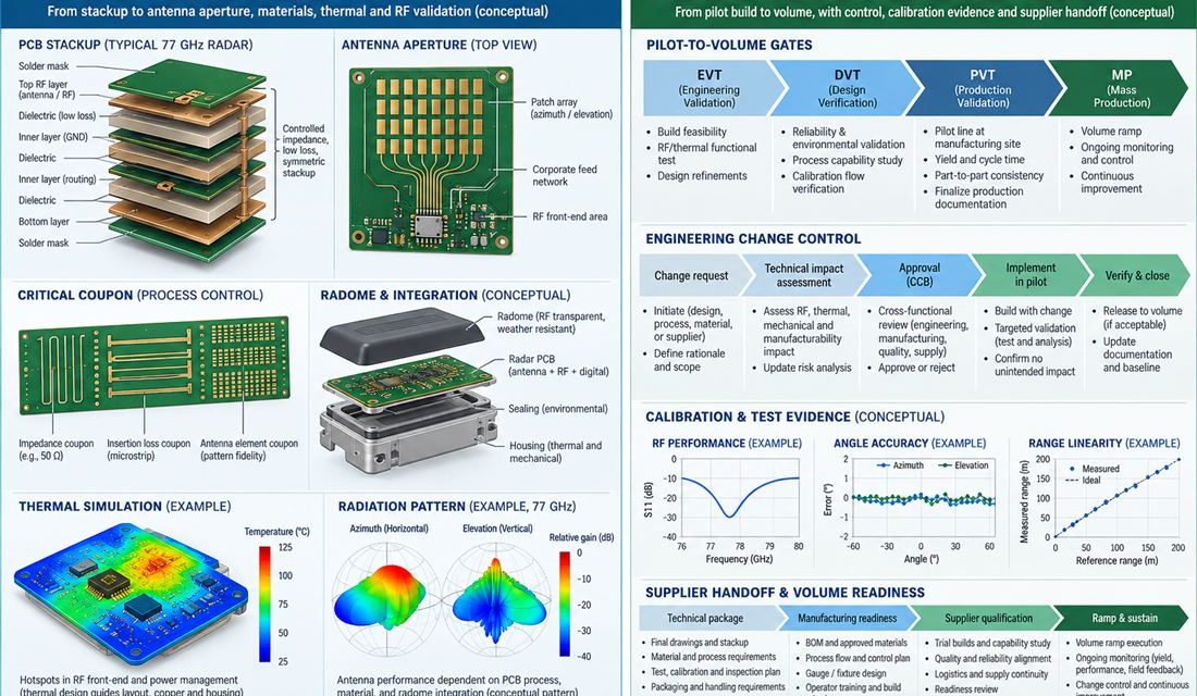
Freezing an Automotive Radar Sensor PCB Without Hiding Open Risk

Automotive Radar Sensor PCB — The final risk in front, corner, and short-range radar sensor boards using a 76–81 GHz antenna aperture, transceiver, processor, and sealed housing is rarely a single missing trace. It is a mixed revision: a stackup updated by procurement, a connector changed by sourcing, an assembly profile copied from another product,...
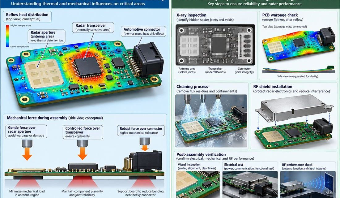
Keeping Radar Geometry Stable Through Automotive Radar Sensor PCB Assembly

Automotive Radar Sensor PCB — Fabrication can meet a drawing and assembly can still move the electrical result. Paste height, reflow warpage, shield force, cleaning chemistry, heat spreaders, and connector rework all act on front, corner, and short-range radar sensor boards using a 76–81 GHz antenna aperture, transceiver, processor, and sealed housing. This production guide...

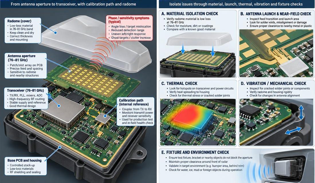
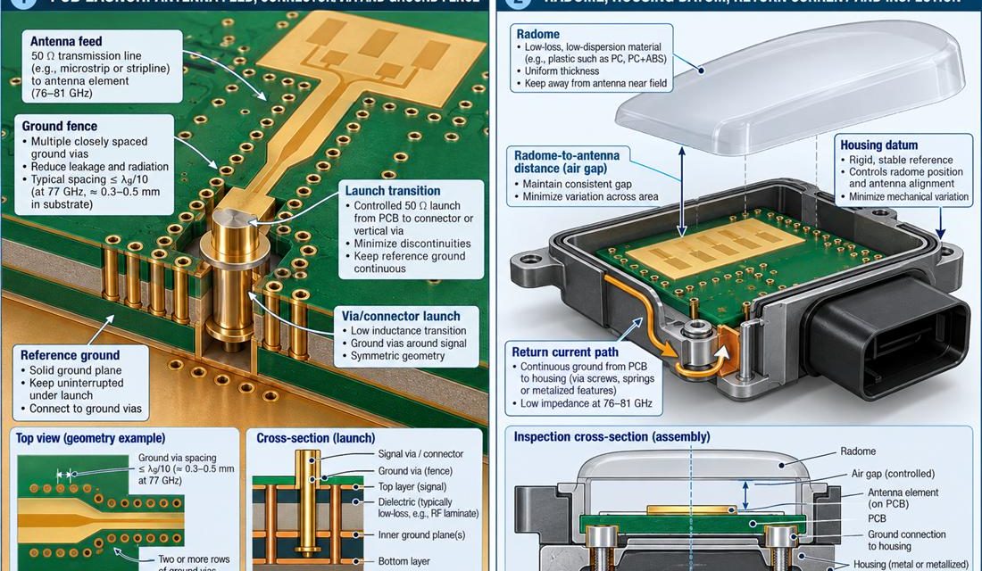
Controlling the 76–81 GHz Launch on an Automotive Radar Sensor PCB

Automotive Radar Sensor PCB — The connector, coax, antenna, sensor flex, or board edge is where a schematic becomes a three-dimensional part. In front, corner, and short-range radar sensor boards using a 76–81 GHz antenna aperture, transceiver, processor, and sealed housing, that interface also has to survive mating force, housing tolerances, and service handling. This...

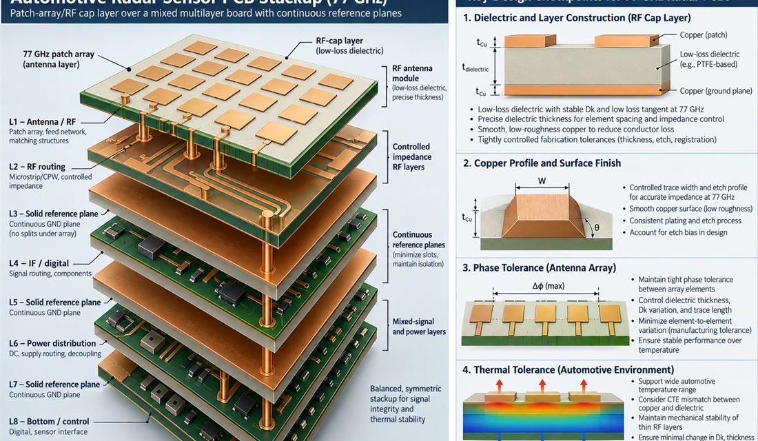
How to Set the Radar Aperture Stackup Before 77 GHz Layout

Automotive Radar Sensor PCB — A layer list is not a stackup release. In front, corner, and short-range radar sensor boards using a 76–81 GHz antenna aperture, transceiver, processor, and sealed housing, the board carries power, digital edges, RF or sensor signals, and mechanical loads at the same time. The Automotive Radar Sensor PCB stackup...