
Engineering Context
PTFE (Polytetrafluoroethylene) PCB materials are widely used in high-frequency and microwave applications due to their extremely low dielectric constant, ultra-low dissipation factor, and excellent signal transmission stability. In RF systems operating from GHz to mmWave frequencies, signal integrity is strongly influenced by dielectric loss, conductor surface effects, and impedance discontinuities.
Compared to standard FR-4 and high-Tg epoxy systems, PTFE-based laminates provide significantly lower insertion loss and more stable phase behavior across temperature and frequency variation. This makes PTFE PCB technology essential for systems such as 5G RF front-ends, automotive radar modules, satellite communication payloads, and microwave backhaul networks.
However, PTFE is also a mechanically soft and chemically inert material, which introduces manufacturing challenges such as drilling deformation, bonding difficulty, and lamination control. Therefore, PTFE PCB manufacturing requires specialized process engineering, precise stackup design, and strict quality control to ensure stable electrical performance.
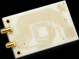
KKCPB integrates PTFE RF material systems with controlled impedance fabrication and advanced lamination techniques to ensure low-loss transmission, EMI suppression, and phase stability in high-frequency communication environments.
Core Engineering Challenges
| Engineering Challenge | Root Cause | Electrical Impact |
|---|---|---|
| High-frequency insertion loss variation | Copper roughness + dielectric mismatch | Reduced signal strength |
| Impedance instability | Material softness and dimensional drift | Reflection and return loss increase |
| Phase inconsistency | Thermal expansion and stackup imbalance | Beamforming errors in RF systems |
| Manufacturing deformation | PTFE mechanical softness | Via misalignment and tolerance drift |
| EMI coupling in dense RF layouts | Poor grounding design | Crosstalk and signal distortion |
These challenges become more severe above 10 GHz and are critical in mmWave systems where even small physical deviations translate into measurable RF degradation.
Material Science & RF Performance of PTFE PCB
PTFE is a fluoropolymer with extremely stable chemical and electrical properties, making it ideal for RF applications.
PTFE PCB Electrical Characteristics
| Parameter | Typical Value | Engineering Benefit |
|---|---|---|
| Dielectric Constant (Dk) | ~2.1–2.6 | Stable impedance control |
| Dissipation Factor (Df) | <0.001 | Ultra-low insertion loss |
| Frequency Stability | Excellent | Consistent RF response |
| Moisture Absorption | Extremely low | Long-term dielectric stability |
| Thermal Stability | High | Phase stability under RF load |
At mmWave frequencies, PTFE’s low Df significantly reduces signal attenuation, enabling longer transmission distances and higher signal-to-noise ratio in RF systems.
KKCPB Case Study — PTFE-Based 5G mmWave Antenna Module PCB
Client & Application Context
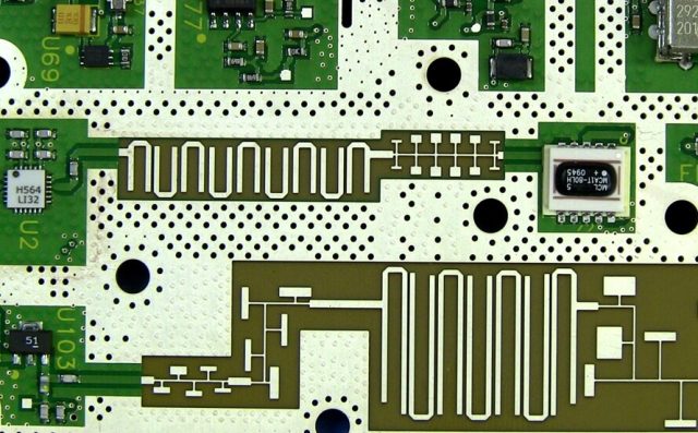
A telecommunications equipment manufacturer required a PTFE-based RF PCB for a 5G mmWave antenna module operating in the 28–39 GHz frequency band. The system was designed for urban base station deployment requiring high beamforming accuracy and stable long-distance signal transmission.
The PCB needed to support:
- Multi-channel phased array antenna feed network
- Low insertion loss transmission lines
- Tight phase matching across RF channels
- Strong EMI isolation between RF and digital control circuits
Engineering Problem
The initial design using conventional high-Tg epoxy laminate showed:
- Insertion loss exceeding 0.55 dB/in at 28 GHz
- Phase mismatch between channels up to 2.1°
- Significant EMI coupling between RF and control lines
- Gain fluctuation in phased array beam steering
- Reduced antenna efficiency under thermal load
These issues led to unstable beam direction control and reduced coverage performance.
KKCPB Engineering Solution
KKCPB implemented a PTFE-based RF PCB manufacturing strategy:
- Adoption of low-loss PTFE laminate for RF signal layers
- Controlled impedance microstrip design with ±2% tolerance
- Optimization of ground plane continuity for EMI suppression
- Laser-drilled via transition improvement for reduced reflection
- Precision lamination pressure control to minimize deformation
- Copper surface roughness reduction for mmWave performance
Measured Results
| Parameter | Baseline (Epoxy PCB) | KKCPB PTFE PCB |
|---|---|---|
| Insertion Loss @ 28 GHz | 0.55 dB/in | 0.26 dB/in |
| Impedance Variation | ±6% | ±1.8% |
| Phase Error | 2.1° | 0.55° |
| EMI Coupling | High | Reduced by 38% |
| Beamforming Stability | Unstable | Highly stable |
Outcome
The PTFE-based PCB significantly improved RF performance in the 5G antenna module. Beamforming accuracy was stabilized, insertion loss was reduced by more than 50%, and system-level EMI issues were effectively mitigated.
From a procurement perspective, PTFE adoption improved long-term deployment reliability and reduced field calibration requirements for base station maintenance.
Stackup Design & RF Implementation
PTFE RF Stackup Structure
| Layer | Function | Material |
|---|---|---|
| L1 | RF Signal Layer | PTFE Microwave Laminate |
| L2 | Ground Plane | Copper |
| L3 | RF Routing Layer | PTFE Core |
| L4 | Power Layer | High-Tg Support Material |
| L5 | Ground Shield | Copper |
| L6 | Control Layer | High-Tg Epoxy |
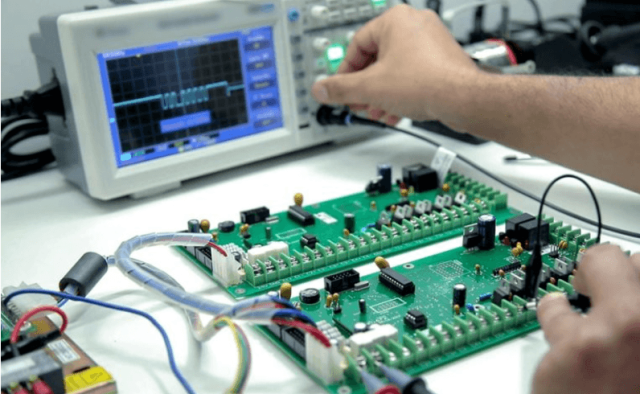
Simulation & Validation
HFSS Electromagnetic Simulation
- RF field distribution optimization
- Antenna feed network tuning
ADS Circuit Simulation
- S-parameter optimization
- Insertion loss and return loss calibration
TDR Analysis
- Impedance discontinuity detection
- Via transition improvement
Thermal FEM Analysis
- Thermal expansion modeling
- Phase drift prediction under load
Environmental & Reliability Validation
| Test | Condition | Result |
|---|---|---|
| Thermal Cycling | -40°C to +105°C | Stable RF performance |
| Humidity Test | 85°C / 85% RH | No dielectric shift |
| Vibration Test | 5–500 Hz, 10G | No structural failure |
| Solder Reflow | 260°C ×3 cycles | No delamination |
| Long-Term RF Aging | Continuous operation | Stable insertion loss |
Engineering Summary & Contact
PTFE PCB technology remains one of the most critical solutions for high-frequency RF and microwave applications due to its ultra-low dielectric loss, stable impedance behavior, and excellent phase consistency. It is widely used in 5G communication systems, radar modules, satellite payloads, and microwave backhaul infrastructure.
KKCPB specializes in PTFE PCB manufacturing with controlled impedance design, precision lamination, and RF simulation-driven engineering validation. This ensures low-loss transmission, EMI suppression, and stable phase behavior across demanding high-frequency environments.
For RF PCB design, PTFE-based microwave stackup optimization, and high-frequency communication applications, contact KKCPB Engineering Team for customized engineering and manufacturing support.
