
Engineering Context
The rapid evolution of wireless communication systems has significantly increased the performance requirements of RF transceiver modules. Modern communication platforms such as 5G base stations, private networks, satellite communication terminals, WiFi 7 devices, IoT gateways, and defense communication systems require PCB solutions capable of supporting high-frequency signal transmission, low insertion loss, precise impedance control, and excellent electromagnetic compatibility.
An RF Transceiver PCB serves as the electrical foundation connecting RF amplifiers, mixers, filters, antennas, frequency converters, and digital processing units. Unlike conventional digital PCBs, RF transceiver boards operate at GHz and mmWave frequencies where small variations in dielectric constant, copper roughness, trace geometry, and layer structure can significantly affect signal quality.
At high frequencies, engineers must carefully control:
- Transmission line impedance
- Phase consistency
- Insertion loss
- Return loss
- EMI interference
- Thermal stability
- RF power handling capability
Material selection is one of the most important factors affecting RF performance. High-frequency laminates such as RO4003C PCB, RO4350B PCB, Duroid 5880 PCB, PTFE PCB, and ceramic PCB provide lower dielectric loss and better phase stability compared with standard FR-4 materials.
For RF system developers and procurement teams, choosing an experienced RF PCB manufacturer is essential. A qualified supplier must provide not only fabrication capability but also RF engineering support, stackup optimization, simulation verification, and production consistency.
KKCPB provides advanced RF Transceiver PCB manufacturing solutions, supporting wireless communication companies with high-frequency PCB fabrication, RF stackup design, controlled impedance manufacturing, and complete reliability validation for next-generation communication systems.
Core Engineering Challenges
| Engineering Challenge | Root Cause | Engineering Impact |
|---|---|---|
| High insertion loss at GHz frequencies | Dielectric loss and copper surface roughness | Reduced RF transmission efficiency |
| Impedance mismatch | Incorrect trace geometry or dielectric variation | Signal reflection and reduced sensitivity |
| Phase instability | Material Dk variation and thermal expansion | Beamforming accuracy degradation |
| EMI interference | Dense RF and digital integration | Crosstalk and signal distortion |
| Thermal stress | High RF power operation | Performance drift and reliability issues |
| Miniaturization pressure | Compact wireless module design | Limited routing space |
These challenges are critical in 5G Module PCB, RF Front-End PCB, Microwave Module PCB, and mmWave Communication PCB applications where signal integrity directly determines system performance.
Material Science & Dielectric Performance of RF Transceiver PCB
RF transceiver applications require PCB materials with stable electrical characteristics over wide frequency ranges.
High-Frequency PCB Material Comparison
| Material | Dk Value | Df Value | Application Benefit |
|---|---|---|---|
| RO4003C PCB | ~3.38 | 0.0027 @10GHz | Cost-effective RF performance |
| RO4350B PCB | ~3.48 | 0.0037 @10GHz | High-frequency communication modules |
| Duroid 5880 PCB | ~2.20 | 0.0009 @10GHz | Ultra-low-loss microwave circuits |
| PTFE PCB | 2.1–3.5 | Very low loss | mmWave applications |
| Ceramic PCB | 6–10+ | Extremely stable | High-power RF systems |
Key RF Performance Parameters
| Parameter | Engineering Importance |
|---|---|
| Dielectric Constant Stability | Maintains phase accuracy |
| Dissipation Factor | Determines signal attenuation |
| Copper Roughness | Influences conductor loss |
| CTE Control | Prevents dimensional variation |
| Moisture Resistance | Maintains electrical consistency |
| Thermal Conductivity | Supports RF power operation |
For wireless communication applications, RF engineers often select RO4003C PCB or similar high-frequency laminates because they provide a balance between electrical performance, manufacturing reliability, and production cost.
RF Transceiver PCB Design Considerations
Controlled Impedance Design
RF transmission lines require precise impedance control to minimize reflection.
KKCPB engineering practices include:
- Microstrip and stripline optimization
- Differential impedance matching
- Trace width calculation
- Dielectric thickness control
- TDR verification
Typical impedance targets:
| Interface | Impedance Requirement |
|---|---|
| RF Transmission Line | 50Ω |
| Differential RF Interface | 100Ω |
| High-Speed Digital | 85Ω–100Ω |
EMI Control and RF Isolation
Modern RF transceiver modules integrate analog, digital, and power circuits on compact boards.
EMI optimization strategies include:
- Dedicated RF ground layers
- Via fence structures
- Shielding zones
- Optimized return current paths
- Component placement separation
These methods reduce unwanted coupling between RF channels and improve system sensitivity.
KKCPB Case Study — 5G Wireless Communication RF Transceiver PCB
Client & Application Context
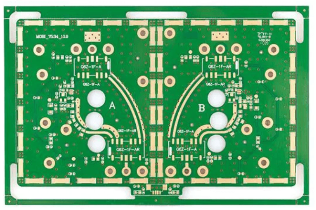
A global communication equipment manufacturer required a high-frequency PCB solution for a compact 5G RF transceiver module.
The product included:
- 5G RF front-end circuits
- Power amplifier units
- Frequency conversion circuits
- Antenna interface networks
- High-speed digital control circuits
The customer required a PCB platform capable of supporting multi-band communication while maintaining stable RF performance under continuous operation.
Engineering Problem
The initial PCB design faced several issues:
- Excessive insertion loss at high frequency
- RF channel phase mismatch
- EMI coupling between RF and digital circuits
- Thermal drift during high-power transmission
- Limited routing space in compact modules
Initial evaluation showed:
- Impedance variation above ±6%
- Phase deviation exceeding 1.2°
- Increased RF calibration requirements
- Reduced transmission efficiency
The customer needed a reliable RF PCB manufacturing partner to optimize both electrical performance and manufacturability.
KKCPB Engineering Solution
KKCPB developed a customized RF Transceiver PCB solution.
Material Selection
Selected:
- Low-loss RF laminate for signal layers
- High-performance copper foil
- Controlled dielectric thickness
RF Stackup Optimization
Implemented:
- Dedicated RF layers
- Ground reference planes
- Optimized dielectric spacing
- Controlled impedance structures
Signal Integrity Improvement
Engineering optimization included:
- RF trace width adjustment
- Differential routing optimization
- Via transition improvement
- EMI isolation zones
Simulation and Verification
KKCPB performed:
- HFSS electromagnetic simulation
- ADS RF circuit analysis
- TDR impedance measurement
- VNA S-parameter testing
- Thermal FEM analysis
Measured Results
| Parameter | Target Requirement | KKCPB Result |
|---|---|---|
| Impedance Variation | ±5% | ±1.6% |
| Insertion Loss @28GHz | <0.8 dB/in | 0.52 dB/in |
| Phase Deviation | <1° | 0.38° |
| Return Loss (S11) | < -15dB | -19.2dB |
| EMI Reduction | Required | Improved 32% |
| Thermal Drift | Minimized | Stable |
Project Outcome
The optimized RF Transceiver PCB achieved:
- Improved wireless signal integrity
- Lower RF transmission loss
- Reduced EMI interference
- Better phase consistency
- Higher production stability
The customer successfully integrated the PCB platform into commercial 5G communication equipment.
Stackup Design & RF Implementation
Representative 8-Layer RF Transceiver PCB Stackup
| Layer | Function | Material |
|---|---|---|
| L1 | RF Signal Layer | Low Loss RF Material |
| L2 | Ground Plane | Copper |
| L3 | Digital Control Signal | High TG PCB |
| L4 | Power Distribution | Heavy Copper |
| L5 | RF Routing Layer | RF Laminate |
| L6 | Ground Plane | Copper |
| L7 | High-Speed Digital Layer | Low Loss Material |
| L8 | Mechanical Layer | Standard PCB Material |
Simulation & Validation
HFSS Simulation
Applied for:
- RF field distribution
- Antenna interface optimization
- EMI coupling analysis
- Transmission line performance
ADS Simulation
Used for:
- RF circuit modeling
- Gain optimization
- S-parameter prediction
TDR Testing
Used for:
- 50Ω impedance verification
- Production consistency evaluation
Thermal FEM Analysis
Used for:
- Power amplifier temperature analysis
- Heat distribution optimization
- Thermal reliability prediction
Physical VNA testing confirmed simulation results and ensured stable RF performance.
Environmental & Reliability Validation
| Test | Condition | Result |
|---|---|---|
| Thermal Cycling | -40°C ↔ +125°C, 1000 cycles | No delamination |
| High Temperature Operation | 150°C continuous | Stable RF performance |
| Humidity Test | 85°C / 85% RH | No dielectric degradation |
| Vibration Test | 5–500Hz, 10G | No mechanical failure |
| Solder Reflow | 260°C ×3 cycles | No warpage |
| RF Power Stress Test | Continuous transmission | Stable insertion loss |
These reliability tests confirm that KKCPB RF Transceiver PCB solutions maintain electrical performance under demanding wireless communication environments.
Engineering Summary
RF communication systems require PCB solutions capable of delivering stable signal transmission, precise impedance control, low insertion loss, and strong electromagnetic performance.
A high-performance RF Transceiver PCB is not simply a multilayer circuit board. It requires careful material selection, RF stackup engineering, simulation verification, manufacturing control, and reliability testing.
KKCPB provides advanced RF PCB solutions for:
- 5G Communication Systems
- RF Front-End Modules
- Microwave Equipment
- Satellite Communication
- IoT Wireless Devices
- mmWave Applications
With expertise in high-frequency materials, controlled impedance fabrication, RF simulation, and precision manufacturing, KKCPB helps global engineers and procurement teams develop reliable wireless communication products with consistent RF performance.
