What Is an RF Trace PCB?
An RF Trace PCB is a specialized RF PCB where signal routing is designed as controlled transmission lines to carry high-frequency signals with minimal loss and distortion.
In RF Trace PCB design, traces are no longer simple connections—they function as engineered RF signal paths, where geometry, materials, and layout directly affect performance.
Typical RF trace structures used in RF PCB design include:
- Microstrip RF traces (outer layer routing)
- Stripline RF traces (internal layer routing)
At high frequencies, even minor variations in RF trace width, spacing, or dielectric thickness can cause impedance mismatch and signal degradation.
In an RF Trace PCB, every trace is part of the RF system.
Why RF Trace PCB Design Is Critical
The performance of an RF PCB depends heavily on how RF traces are designed. Poor RF trace PCB design can lead to:
- Impedance mismatch and signal reflection
- Increased insertion loss in RF traces
- Phase distortion in high-frequency signals
- Reduced efficiency in RF transmission
In applications such as 5G, wireless communication, IoT devices, and radar systems, RF trace PCB quality directly determines system performance.
Key principle:
RF Trace PCB design = signal performance control.
RF Trace Loss Mechanisms in RF PCBs
To optimize RF Trace PCB performance, it is essential to understand where signal loss originates:
1. Dielectric Loss in RF PCB Materials
Loss caused by energy dissipation in the substrate, increasing with frequency
2. Conductor Loss in RF Traces
Skin effect increases resistance as frequency rises
3. Copper Surface Roughness
Rough copper in RF traces increases attenuation
4. Impedance Discontinuities
Occurs at vias, connectors, and abrupt RF trace geometry changes
5. Radiation Loss in RF PCB Layouts
Improper grounding causes RF signals to radiate
These loss mechanisms must be minimized in any high-performance RF Trace PCB design.
RF Trace PCB Design Methodology
A structured RF Trace PCB design process ensures optimal signal integrity:
1. Controlled Impedance Design
- Maintain 50Ω single-ended or 100Ω differential impedance
- Ensure consistent RF trace geometry across the PCB
2. Transmission Line Selection
- Microstrip RF traces → easier routing, higher radiation
- Stripline RF traces → better shielding, lower EMI
3. RF PCB Stack-Up Optimization
- Stable dielectric thickness
- Continuous ground reference planes
4. Minimize RF Trace Discontinuities
- Avoid sharp corners in RF traces
- Reduce layer transitions and vias
5. Optimize Return Path
- Ensure uninterrupted ground beneath RF traces
- Avoid routing RF traces across split planes
Effective RF Trace PCB design is about controlling the entire electromagnetic environment.
Practical RF Trace PCB Layout Rules
These practical rules help engineers design reliable RF Trace PCBs:
- Keep RF traces short, direct, and consistent
- Avoid unnecessary vias in RF trace routing
- Use via stitching (via fencing) along RF traces
- Maintain constant impedance along the RF trace path
- Separate RF traces from digital and power routing
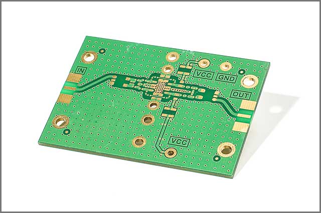
- Place RF connectors close to the signal source
- Avoid 90° bends—use smooth curves or 45° angles
Golden Rule:Every discontinuity in an RF trace reduces RF PCB performance.
Materials for RF Trace PCBs
Material selection is critical in RF Trace PCB performance:
- Low-loss RF PCB materials (low Df)
Reduce dielectric loss in RF traces - Stable dielectric constant (Dk)
Ensures consistent RF trace impedance - Smooth copper foil
Minimizes conductor loss in RF traces - Hybrid stack-ups
Combine RF materials with FR-4 to optimize cost
At higher frequencies, especially in mmWave RF PCB designs, material choice becomes a key performance factor.
Common RF Trace PCB Design Mistakes
Avoid these common RF Trace PCB design errors:
- Ignoring impedance control in RF traces
- Excessive use of vias in RF PCB routing
- Routing RF traces over split ground planes
- Mixing RF and high-speed digital signals without isolation
- Using standard materials for high-frequency RF PCB designs
These mistakes often result in poor RF performance and failed testing.
Final Thoughts
RF Trace PCB design is a critical discipline in modern RF engineering. A high-performance RF PCB requires:
- Precise RF trace impedance control
- Minimization of RF trace loss mechanisms
- Optimized RF PCB stack-up and materials
- Clean and continuous RF signal paths
At KKPCB, we specialize in RF Trace PCB design and manufacturing, providing controlled impedance, low-loss materials, and precision fabrication to ensure reliable high-frequency performance.
