
Table of Contents
A robot joint can miss a taught position even when the control algorithm is unchanged. The hidden cause in a Robotics PCB is often a power-integrity problem: a long DC-link loop, an undersized return path, or a gate-drive transient that moves the controller reference while the motor current changes. A Robotics PCB in a joint controller must carry power switching, encoder feedback, communications, and safety functions without letting the high-current loop corrupt the low-level control signals.
This article approaches the board from the motion engineer’s bench. It connects the current path, thermal spreading, grounding, connector choice, and production checks so a project manager can release a repeatable motor-drive module rather than chase intermittent position faults in the robot.
Why motion errors begin in the power loop
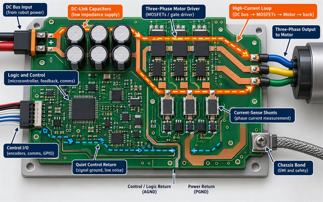
The Robotics PCB motor driver creates the most aggressive electrical event on the board. During acceleration, the DC bus feeds the bridge; during braking, energy returns through the bus and protection network. The loop area, capacitor placement, and return inductance determine how much of that event appears at the logic reference. Begin the PCB design review by drawing the complete switching loop over the physical stackup, not only on the schematic.
For a Smart Factory cell or collaborative arm, the same Robotics PCB may see repeated start-stop motion, cable flexing, and regenerative events. A Robotics PCB layout that behaves on a resistive bench load may show ringing when the real joint cable, motor inductance, and brake resistor are connected. Treat cable length and connector inductance as part of the released electrical model.
Shape the motor-current path
Place DC-link capacitors next to the bridge’s power pins, keep the positive and negative paths adjacent, and avoid routing the return through a general-purpose ground plane. For a Robotics PCB carrying high current, a broad copper region with multiple thermal and electrical vias can be more predictable than a narrow trace that changes layer at a connector. Coordinate the stackup and copper thickness with PCB materials and fabrication capability before freezing the geometry.
The current-sense shunt needs its own Kelvin path. Confirm the controlled impedance of any fast gate or communication route. Route the sense pair from the shunt pads to the amplifier inputs as a matched, quiet connection, and keep gate-drive return current out of that pair. A copper pour that looks continuous can still create a voltage error when a pulse current shares its neck-down. Give the driver, shunt, and local ceramic capacitors a defined placement zone, then connect that zone to the control reference at one planned point.
Use thermal copper as an electrical decision
Motor losses are not solved by adding copper after routing is complete. The Robotics PCB copper geometry changes loop inductance, heat spreading, solder-joint stress, and the distance between a hot switch node and a sensitive input. Define the expected duty cycle as a design target, identify the hottest component region, and give the fabricator a drawing that distinguishes power copper from signal copper. The PCB manufacturing review should cover via fill, annular ring, solder-mask dams, and the risk of copper imbalance through the joint stack.
Protect the control return
The Robotics PCB microcontroller, encoder receiver, and safety monitor need a reference that does not move with the bridge current. Keep the control region away from the switching node, place its decoupling at each device, and route communication pairs with a continuous reference. A high-frequency PCB discipline is useful here even when the motor command bandwidth is lower than an RF link: fast gate edges still need a short return path.
Separate signal ground from chassis bonding only when the system-level EMC strategy defines how the two meet. A shield pigtail that lands beside the encoder receiver can inject a transient into the measurement reference. Put the cable shield entry, transient protection, and connector datum on the mechanical drawing. If the joint includes a brake or safety relay, document the power electronics PCB copper and keep its coil current keep its coil current and flyback path out of the encoder and current-sense region.
Validate acceleration and braking
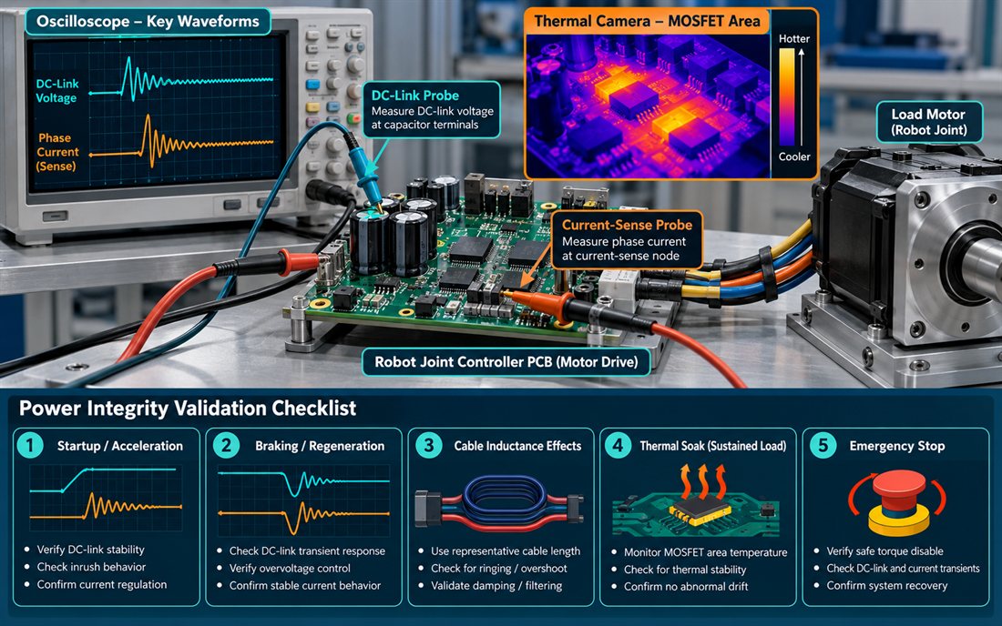
Robotics PCB validation should use the actual motor cable, representative load, and the firmware motion profile. Capture the DC-link at the capacitor terminals, the current-sense output, the control reference, and the fault line during startup, acceleration, deceleration, and emergency stop. Treat the waveforms as engineering evidence for the design review, not as a customer measurement claim. A typical target is to keep overshoot and reference movement inside the controller and device limits with margin for cable variation.
Robotics PCB thermal validation must follow electrical validation. Run a repeated motion cycle until the bridge, shunt, connector, and board hot spots approach steady state. Compare the temperature rise of the power region with the drift of the current-sense offset. If the offset changes only after the joint warms, inspect copper spreading and Kelvin symmetry before modifying the control loop. Use signal integrity review and PCB assembly inspection to verify solder coverage on the shunt, bridge, and high-current connector.
Release a serviceable joint controller
Before release, check five items on the Robotics PCB: the power loop is dimensioned on the released stackup; the Kelvin sense pair has no shared high-current neck; the encoder and safety returns have a documented reference; the connector and shield strategy are on the mechanical drawing; and the test fixture can access the bus, sense, and fault nodes without unsafe probing. For the pilot build, use PCB fabrication coupons or sample pieces to confirm the finished copper and via construction before a long production run.
Keep a short Robotics PCB change-control record for cable length, motor variant, brake resistor, and firmware motion profile. A new actuator can change regeneration even when the board outline is identical. If the project later adds a faster bus, review PCB prototyping data, PCB finish compatibility, and connector rework instructions together. This prevents a “minor” motion option from creating a new EMC or thermal risk.
Sources: power-device and motor-driver manufacturer application notes, Analog Devices material on current sensing and grounding, Qorvo and Würth references for return-current control, laminate manufacturer data for thermal construction, and KKPCB capability pages for design, materials, fabrication, assembly, and prototyping. Values in this article are typical design targets or engineering ranges, not customer test results.
