
Engineering Context
As electronic systems continue to increase in power density, thermal management has become one of the most critical challenges in PCB engineering. Modern applications including electric vehicles, industrial automation, renewable energy systems, power converters, motor drives, LED systems, aerospace electronics, and high-performance computing require PCB solutions capable of efficiently transferring heat away from high-power components.
A Thermal Management PCB is designed to control heat generation, conduction, and dissipation through optimized material selection, copper structures, thermal vias, and mechanical integration. Unlike standard PCB designs, thermal-focused circuit boards must consider not only electrical performance but also thermal resistance, temperature distribution, reliability under thermal cycling, and long-term mechanical stability.
High-power electronic components such as MOSFETs, IGBTs, power amplifiers, processors, and RF transmitters generate significant heat during operation. Without effective thermal management, excessive temperature can accelerate component aging, increase electrical resistance, create solder joint fatigue, and reduce system lifetime.
Modern thermal PCB technologies include:
- Metal Core PCB (MCPCB)
- Ceramic PCB
- Aluminum Nitride PCB
- Heavy Copper PCB
- Copper-inlay PCB
- High thermal conductivity laminate PCB
- Hybrid thermal stackup PCB
Selecting the correct thermal solution requires balancing thermal conductivity, electrical insulation, manufacturability, cost, and reliability.
KKCPB provides advanced Thermal Management PCB solutions integrating material engineering, thermal simulation, copper optimization, and reliability testing for demanding high-power electronic applications.
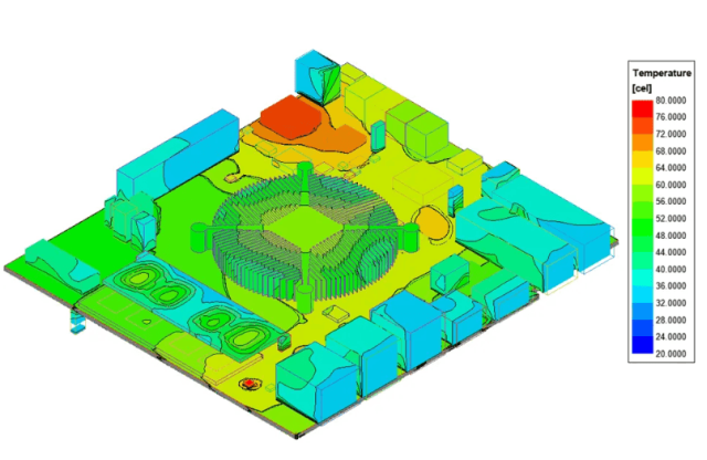
Core Engineering Challenges
| Engineering Challenge | Root Cause | Engineering Impact |
|---|---|---|
| Excessive component temperature | High power density and insufficient heat path | Reduced component lifetime |
| Thermal hotspot formation | Uneven copper distribution | Localized failure risk |
| PCB warpage under heat cycles | CTE mismatch between materials | Assembly reliability problems |
| Solder joint fatigue | Repeated thermal expansion | Intermittent electrical failure |
| Limited heat spreading capability | Low thermal conductivity substrate | Reduced system efficiency |
| Electrical and thermal design conflicts | High copper requirements affecting impedance | Signal integrity issues |
These challenges are especially important in Power Electronics PCB, Automotive Electronics PCB, Industrial Automation PCB, and RF Power Amplifier PCB applications where continuous operation and reliability are essential.
Material Science & Thermal Performance
Material selection determines the thermal performance of a PCB. Different applications require different thermal conductivity levels and mechanical characteristics.
Thermal PCB Material Comparison
| Material | Thermal Conductivity | Typical Application | Engineering Benefit |
|---|---|---|---|
| Standard FR-4 PCB | 0.3–0.5 W/m·K | General electronics | Low cost |
| Heavy Copper PCB | Enhanced copper heat path | Power circuits | Improved current capacity |
| Aluminum PCB | 1–3 W/m·K | LED, power modules | Efficient heat spreading |
| Ceramic PCB | 20–170 W/m·K | High-power RF, aerospace | Excellent thermal performance |
| Aluminum Nitride PCB | 140–180 W/m·K | Advanced power electronics | High thermal conductivity with electrical insulation |
| Copper Core PCB | Very high | Extreme power applications | Maximum heat dissipation |
Key Thermal Design Parameters
| Parameter | Engineering Importance |
|---|---|
| Thermal Conductivity | Determines heat transfer efficiency |
| CTE Matching | Prevents mechanical stress |
| Copper Thickness | Improves current carrying capability |
| Thermal Via Density | Enhances vertical heat transfer |
| Dielectric Thickness | Affects thermal resistance |
| Material Stability | Maintains performance during thermal cycling |
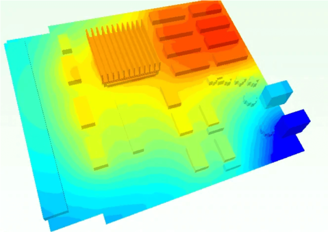
Compared with traditional FR-4 materials, ceramic PCB and metal-based thermal solutions provide significantly improved heat dissipation capability for high-power electronic systems.
Thermal Management PCB Design Strategies
Thermal Via Optimization
Thermal vias create vertical heat transfer paths between component layers and internal copper planes.
Engineering considerations include:
- Via diameter optimization
- Via density distribution
- Copper-filled via structures
- Thermal pad connection design
Heavy Copper PCB Technology
Heavy copper PCB technology uses thicker copper layers to improve:
- Current carrying capability
- Heat spreading
- Power reliability
- Mechanical strength
Typical applications include:
- Battery management systems
- Motor controllers
- Power converters
- Industrial control systems
Ceramic PCB Thermal Solutions
Ceramic substrates such as Alumina PCB and Aluminum Nitride PCB provide:
- High thermal conductivity
- Excellent electrical insulation
- Low thermal expansion
- High-temperature stability
These materials are widely used in:
- RF power modules
- Aerospace electronics
- Automotive power systems
- High-temperature sensors
KKCPB Case Study — Thermal Management PCB for Industrial Motor Control System
Client & Application Context
A global industrial automation company required a high-power PCB solution for a next-generation motor control unit used in smart factory equipment.
The application included:
- High-current motor drivers
- Power MOSFET switching circuits
- Industrial communication modules
- Temperature monitoring circuits
- Continuous 24/7 operation
The customer required a PCB platform capable of maintaining stable operation under high electrical load and elevated ambient temperature.
Engineering Problem
The original PCB design using standard FR-4 experienced several thermal issues:
- MOSFET junction temperature exceeded design limits
- Localized heat accumulation near power components
- PCB temperature gradient exceeded acceptable range
- Solder joints showed fatigue after thermal cycling
- System efficiency decreased during continuous operation
Thermal simulation indicated:
- Maximum hotspot temperature above 105°C
- Poor heat distribution across PCB surface
- Increased reliability risk under long-term operation
The customer required improved thermal performance without increasing overall product size.
KKCPB Engineering Solution
KKCPB developed a customized thermal PCB solution using a hybrid thermal structure.
The engineering improvements included:
- Aluminum core thermal PCB design
- Optimized copper thickness distribution
- High thermal conductivity dielectric layer
- Thermal via arrays beneath power devices
- Enlarged copper heat spreading areas
- Improved component placement strategy
- Thermal simulation before fabrication
Validation methods included:
- Thermal FEM simulation
- Infrared thermal imaging
- Electrical load testing
- Thermal cycling verification
Measured Results
| Parameter | Original Design | KKCPB Thermal PCB Result |
|---|---|---|
| Maximum Temperature | 105°C | 82°C |
| Thermal Resistance | Baseline | Reduced by 38% |
| Hotspot Temperature Difference | 25°C | 11°C |
| Continuous Current Capability | Standard | Increased by 35% |
| PCB Warpage | 0.18 mm | 0.08 mm |
| Thermal Cycling Reliability | Limited | Passed 1000 cycles |
Project Outcome
The optimized Thermal Management PCB significantly improved system reliability.
The customer achieved:
- Lower operating temperature
- Extended component lifetime
- Improved power efficiency
- Reduced thermal failure risk
- Stable operation under continuous load
The solution successfully entered mass production for industrial automation equipment.
Stackup Design & Thermal Implementation
Representative 6-Layer Thermal PCB Stackup
| Layer | Function | Material |
|---|---|---|
| L1 | Component & Power Layer | Heavy Copper |
| L2 | Thermal Spreading Layer | Aluminum Core |
| L3 | Ground Plane | Copper |
| L4 | Power Distribution | Heavy Copper |
| L5 | Signal Routing | High-TG PCB Material |
| L6 | Bottom Thermal Layer | Metal Heat Dissipation Layer |
Simulation & Validation
Thermal FEM Simulation
Used for:
- Temperature distribution analysis
- Heat flow optimization
- Component thermal prediction
- Material comparison
CFD Thermal Analysis
Used for:
- Airflow evaluation
- Cooling structure optimization
- Heat sink integration analysis
Electrical Simulation
Used for:
- Current density analysis
- Power loss estimation
- Voltage drop evaluation
Infrared Thermal Testing
Used for:
- Real-time hotspot detection
- Simulation verification
- Production validation
The combination of simulation and physical testing ensures thermal performance matches engineering requirements.
Environmental & Reliability Validation
| Test | Condition | Result |
|---|---|---|
| Thermal Cycling | -40°C ↔ +125°C, 1000 cycles | No delamination |
| High Temperature Storage | 150°C, 1000 h | Stable structure |
| Power Load Test | Continuous rated current | Passed |
| Humidity Test | 85°C / 85% RH | No performance degradation |
| Solder Reflow | 260°C ×3 cycles | No warpage failure |
| Vibration Test | Industrial vibration profile | No mechanical damage |
These tests confirm the reliability of KKCPB Thermal Management PCB solutions under demanding operating environments.
Engineering Summary & Contact
Thermal management has become a fundamental requirement for modern high-power electronics. A reliable Thermal Management PCB must combine efficient heat dissipation, electrical performance, mechanical stability, and long-term reliability.
From aluminum PCB and heavy copper PCB solutions to ceramic PCB and advanced thermal multilayer designs, selecting the right technology depends on power density, operating temperature, and system requirements.
KKCPB provides customized thermal PCB solutions for:
- Automotive Electronics PCB
- Industrial Automation PCB
- Power Electronics PCB
- RF Amplifier PCB
- Medical Equipment PCB
- Aerospace Electronics PCB
With expertise in thermal material selection, PCB stackup design, copper optimization, simulation validation, and manufacturing control, KKCPB helps engineers and procurement teams develop reliable high-power electronic systems with improved thermal performance and extended operational lifetime
