
As electronic systems continue moving toward higher frequencies, faster signal transmission, and more demanding operating environments, PCB material selection has become a critical factor affecting product performance.
For RF, microwave, automotive radar, and high-speed communication applications, conventional FR-4 materials may not always provide sufficient electrical stability due to higher dielectric loss and variations in dielectric properties.
High-frequency PCB materials such as RO4835™ laminate are designed to address these challenges by providing low-loss performance, stable dielectric characteristics, and reliable thermal behavior for advanced RF circuit applications.
Selecting the appropriate laminate is not only a material decision but also an important part of PCB design optimization, affecting impedance control, signal integrity, manufacturing consistency, and long-term reliability.
1. Overview of RO4835™ High Frequency Laminate
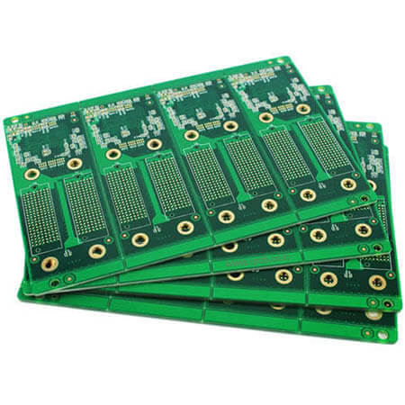
RO4835™ laminate is part of the RO4000® series high-frequency circuit materials developed for RF and microwave applications.
Compared with traditional thermoset materials, RO4835™ provides improved stability against oxidation and maintains consistent electrical performance under elevated temperature conditions.
Key characteristics include:
- Low dielectric loss
- Stable dielectric constant
- High thermal reliability
- Compatibility with standard PCB manufacturing processes
- Suitable performance for high-frequency applications
These characteristics make RO4835™ suitable for applications requiring controlled electrical performance and production scalability.
2. Electrical Properties of RO4835™
Electrical performance is one of the most important considerations when selecting high-frequency PCB materials.
2.1 Stable Dielectric Constant (Dk)
The dielectric constant directly affects:
- Signal propagation speed
- Characteristic impedance
- Phase stability
According to the RO4835™ datasheet, the material provides controlled dielectric constant characteristics, supporting designs requiring stable impedance transmission lines.
Stable Dk helps engineers achieve more predictable RF performance, especially in:
- Antenna designs
- Microwave circuits
- High-speed communication systems
2.2 Low Dissipation Factor
Signal loss becomes increasingly significant as frequency increases.
A low dissipation factor helps reduce:
- Dielectric loss
- Signal attenuation
- Transmission efficiency degradation
This makes RO4835™ suitable for frequency-sensitive applications where maintaining signal quality is critical.
3. Thermal Performance and Reliability
High-frequency PCB materials must maintain stable performance under temperature variations.
RO4835™ provides:
High Glass Transition Temperature (Tg)
The material has a Tg above 280°C, supporting stable dimensional behavior during PCB processing and operation.
Low Thermal Expansion
The material’s thermal expansion characteristics help improve:
- Plated through-hole reliability
- Dimensional stability
- Multilayer PCB consistency
This is particularly important for complex multilayer boards combining different dielectric materials.
4. Advantages of RO4835™ in High Frequency PCB Design
4.1 Improved Signal Integrity
High-frequency signals are sensitive to:
- Material variation
- Impedance changes
- Transmission loss
RO4835™ helps designers maintain stable electrical characteristics through:
- Controlled dielectric properties
- Low-loss transmission
- Reliable impedance performance
4.2 Suitable for Controlled Impedance Applications
For RF and microwave PCB designs, impedance control is essential.
The PCB stack-up design must consider:
- Material thickness
- Copper thickness
- Trace geometry
- Dielectric properties
RO4835™ supports controlled impedance transmission line designs required in high-frequency circuits.
4.3 Manufacturing Compatibility
One advantage of RO4000® series materials is that they can be processed using standard FR-4 PCB manufacturing techniques.
This provides benefits such as:
- Easier production integration
- Reduced manufacturing complexity
- Better production scalability
5. Typical Applications of RO4835™ Laminate

RO4835™ materials are commonly used in applications requiring high-frequency performance.
Automotive Radar Systems
Automotive radar requires stable signal transmission at high frequencies.
Applications include:
- 77GHz radar modules
- Vehicle sensing systems
- Advanced driver assistance systems (ADAS)
Material stability directly affects radar accuracy and reliability.
RF and Microwave Equipment
High-frequency laminates are widely used in:
- RF modules
- Microwave circuits
- Power amplifiers
- Communication equipment
These applications require low signal loss and stable electrical performance.
Antenna Systems
Antenna performance depends heavily on PCB material characteristics.
Important factors include:
- Dielectric consistency
- Phase stability
- Low transmission loss
RO4835™ supports reliable antenna performance in demanding RF environments.
6. PCB Design Considerations When Using RO4835™
Although high-frequency materials provide excellent electrical performance, PCB design still requires careful engineering.
Stack-Up Optimization
Engineers should consider:
- Layer arrangement
- Signal reference planes
- Dielectric thickness
A proper stack-up helps achieve the expected RF performance.
Impedance Control
Manufacturing variation can influence impedance.
Key control factors include:
- Trace width tolerance
- Copper thickness
- Lamination accuracy
- Material consistency
Hybrid Material PCB Design
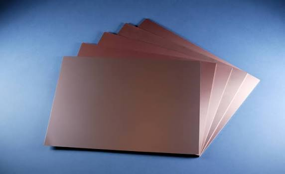
Some products combine high-frequency materials with standard FR-4 layers.
Hybrid stack-up design requires careful evaluation of:
- Material compatibility
- Thermal expansion
- Lamination processes
- Signal transition areas
7. Manufacturing Considerations for RO4835™ PCB Fabrication
High-frequency PCB manufacturing requires stricter process control compared with standard PCBs.
Important factors include:
Layer Registration Accuracy
Precise alignment helps maintain:
- Signal consistency
- Reliable via connections
- Stable electrical performance
Surface Treatment Selection
Surface finishes should consider:
- RF signal requirements
- Assembly process
- Reliability expectations
Electrical Testing
High-frequency PCB verification may include:
- Impedance testing
- TDR measurement
- Electrical inspection
These tests help ensure the fabricated PCB meets design requirements.
Conclusion
RO4835™ laminate provides a reliable material solution for high-frequency PCB applications requiring low loss, stable dielectric performance, and thermal reliability.
From automotive radar and RF communication systems to microwave circuits and antenna applications, selecting the right PCB material plays an essential role in achieving stable signal transmission and long-term product reliability.
However, material selection is only one part of successful high-frequency PCB development. Proper stack-up design, impedance control, manufacturing capability, and engineering verification are equally important for transforming RF designs into production-ready solutions.
