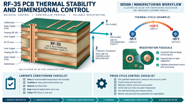
Thermal drift is an electrical problem when a microwave board moves enough to change trace geometry, connector alignment, or plated-hole stress. This article treats RF-35 PCB as a production material choice and focuses on the thermal-mechanical controls that keep a high-frequency design repeatable from panel build through assembly.
Taconic RF-35 typical property tables report a dielectric constant near 3.50 at 1.9 GHz, a low dissipation factor, and a z-axis expansion value that must be considered with the rest of the stack. The numbers are reference values only. The approved supplier datasheet, glass style, resin content, copper treatment, and actual pressed thickness belong in the released stackup.
Table of Contents
1. Identify thermal risk at the project handoff
For an RF-35 PCB, the first question is not “what is the nominal CTE?” It is “which interface is most sensitive to movement?” A long edge launch, a tightly packed via fence, a cavity, and a thin RF core can all react differently during lamination and reflow. Map each interface in the design review and state the controlling dimension: finished dielectric height, hole-to-copper clearance, edge-to-launch distance, or registration to a shield.
Separate in-plane registration requirements from z-axis reliability requirements.
Flag RF launches that share copper with a thermal relief or a split plane.
Identify heavy copper, large copper pours, and dissimilar materials that can pull a panel during pressing.
Define which dimensions are measured on the coupon and which are checked on the product panel.
A thermal-focused high-frequency PCB review should also check the assembly profile. A board that meets its RF geometry at room temperature can still show a shifted connector pin field or a cracked plated hole after repeated heating if the mechanical release notes are incomplete.
2. Control material conditioning and the pressed stackup
The RF-35 PCB stack should name the exact core and prepreg construction, copper foil state, finished dielectric target, and press sequence. RF laminates are not interchangeable simply because two catalogs show similar Dk values. Glass style and resin content change the effective field distribution, while press flow changes the final separation between a trace and its reference plane.
Release checks before lamination
Control
Why it matters
Document it as
Material storage
Moisture and out-time can affect bonding and dimensional behavior.
Incoming inspection and conditioning record.
Press construction
Resin flow and copper balance influence finished dielectric height.
Approved stack drawing and press recipe family.
Copper balance
Unbalanced copper can increase panel bow or local registration shift.
Panelization rule and copper-fill review.
Finished thickness
Impedance depends on the pressed distance, not only nominal material.
Cross-section target and coupon checkpoint.
Use a controlled PCB design model that distinguishes nominal, target, and tolerance values. A good drawing makes it clear which number is used for field-solver work and which number is the acceptance limit after fabrication. If an RF-35 PCB requires a material substitution, recalculate the line geometry instead of treating the substitute as a drop-in.
3. Protect registration through drilling and plating
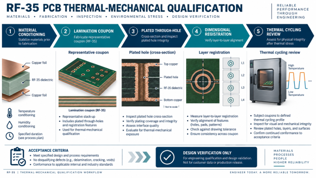
Layer-to-layer registration is the bridge between thermal behavior and RF performance. A via fence that is electrically correct in CAD can lose symmetry when drill wander, press movement, and copper etch are combined. Keep registration targets on the panel, expose the critical RF layer pair in a representative coupon, and leave enough annular ring for the agreed drill process.
For an RF-35 PCB, the drill chart should identify plated through holes, blind or buried vias, controlled-depth features, and any back-drill requirement. Tie the drill strategy to the actual layer map. Do not specify a generic “RF via” without a finished diameter, capture-pad rule, antipad clearance, and reference-plane continuity.
4. Use coupons for verification, not for invented results
A thermal-mechanical coupon should represent the product’s critical construction: the same RF-35 core or prepreg, copper treatment, plated-hole class, and registration features. The coupon can support cross-section review, layer alignment checks, and an agreed impedance test. It does not automatically prove the performance of every signal on the panel.
List the inspection method and acceptance window in the purchase package. Depending on the project, the team may use microsection, dimensional measurement, TDR, or a calibrated fixture. Keep the language precise: “design target,” “typical material value,” and “measured coupon result” are different statements. A PCB manufacturing traveler should point to the same revision-controlled drawing used by design engineering.
5. Complete the assembly and reliability handoff
The thermal loop closes during assembly. Share the approved reflow profile, connector seating limits, shield installation notes, and any no-rework zones with the PCB assembly team. Large thermal pads and ground vias can wick solder away from an RF launch, so the assembly drawing should identify paste apertures and inspection access.
For demanding multilayer programs, KKPCB states capability up to 62 layers and 8 sequential lamination steps. That capability helps when RF and digital layers need physical separation, but the project still needs a realistic press sequence, panel outline, and registration budget. Treat the stackup, thermal process, and coupon as one controlled release.
In summary, a reliable RF-35 PCB is achieved by controlling material conditioning, pressed geometry, registration, and assembly—not by quoting a single CTE number. When the engineering team defines those controls before fabrication, thermal cycling becomes a planned verification step instead of a surprise failure mode for the RF-35 PCB.
Sources: Taconic RF-35 and RF-35P processing guidance and typical property tables; IPC-TM-650 references for dimensional, thermal, and cross-section evaluation; and KKPCB manufacturing capability notes. Typical values are reference data rather than customer measurements; confirm the current supplier datasheet and lot before release.