
An infusion pump controller has to coordinate a motor or actuator, sensing inputs, user controls, alarms, and power management inside one compact assembly. On a Healthcare PCB, the motor drive can create fast, relatively large current changes while flow, pressure, or position circuits may depend on small analog signals. The layout task is to trace both systems from connector to return, identify where their currents meet, and verify the assembled device under its intended conditions. A board layout alone does not establish delivery accuracy or device safety.
Map the Healthcare PCB pump-control and sensing paths
Start from the system block diagram and connector list. Mark motor phases, current sense, encoder or position feedback if present, pressure transducer, flow sensor, door or latch inputs, alarm output, display, battery, charger, and communication ports. The exact mix varies by pump architecture; do not assume that every design uses the same actuator or sensor set. A Healthcare PCB floorplan should place the drive stage, power conversion, low-level signal conditioning, and processor so the electrical paths remain inspectable.
Write down the operating states that change current or sampling behavior: startup, motor stepping, hold or idle, delivery change, sensor read, alarm, battery transition, and charge state where applicable. Identify which supply rails serve each state and whether the sensor reference is shared with a drive or converter return. This schematic-to-layout map is more useful than drawing a generic “noisy” and “quiet” split with no current-path rationale. A Healthcare PCB review should trace those return paths before placement is frozen. A Healthcare PCB should be evaluated with the intended motor, sensors, and harness connected.
Keep motor-output wiring and sensor wiring distinct at connectors when the enclosure and harness allow it. Route pairs with their intended returns, avoid long parallel exposure between motor phases and high-impedance sensor leads, and document shield termination at the board or chassis. Review the complete harness too: an external cable can couple fields into the pressure or flow input even when board traces are well separated. A PCB prototype assembly review should include the real harness, connector keying, and enclosure arrangement. The SMT PCB assembly process should preserve those connector details in the build record.
Contain stepper and motor current loops
For a stepper driver or H-bridge, locate the switching devices, current-sense element, local ceramic decoupling, and bulk capacitance so the high-di/dt loop stays compact. Follow the current through both polarities of the motor winding and through the local DC-link path. Keep the switching node away from sensor input pins, reference components, and long unshielded cable launches. The correct loop depends on the selected driver, recirculation method, supply, and motor; use that device’s data sheet and reference design rather than copying a generic placement.
Texas Instruments’ step-motor drive application note illustrates different drive techniques and current waveforms for particular configurations. Those examples can inform the review, but the actual motor, driver decay mode, current limit, microstep pattern, and firmware timing govern the product’s behavior. Keep the current-sense signal Kelvin-routed from the intended resistor terminals and follow the driver manufacturer’s filtering recommendations. A PCB design review should check that the sense return is not carrying motor load current.
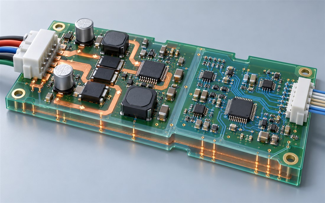
Do not rely on copper distance alone. A switch node with a large voltage edge can couple capacitively; a motor-current loop with a large area can couple magnetically; and a shared impedance can move the local reference. Keep the forward and return paths close, reduce unnecessary switch-node copper, and inspect layer transitions and vias. If a heat spreader or chassis connection is used, review where switching currents flow rather than assuming the metal is electrically quiet. A PCB fabrication review can confirm that the intended copper geometry and layer transitions remain buildable.
Protect flow and pressure signal paths
Identify the sensor output type and its source impedance before choosing a routing strategy. A bridge, piezoresistive pressure sensor, optical flow sensor, Hall element, or other transducer can require a different excitation, filtering, protection, and acquisition path. Place input protection and conditioning near the connector where that reduces exposed high-impedance routing, while preserving access for calibration and electrical test. A Healthcare PCB should state which reference or excitation source the sensor depends on and where its return closes.
Route differential inputs together with consistent geometry and a nearby reference. Keep ADC reference, sensor excitation, and low-level input traces away from motor-phase copper, converter inductors, and fast clocks. Put decoupling close to the analog front-end pins and return it to the appropriate local plane. If the sensor requires excitation switching or multiplexing, plan the settling interval and sample timing in coordination with the actuator state; filtering cannot compensate for sampling an unsettled signal.
Separate digital status lines and alarm loads from high-impedance measurement nodes. If sensor thresholds or compensation values are stored digitally, keep the communication path short and protect the analog reference from processor burst currents. A multilayer PCB stackup can support a continuous signal reference while routing motor power on an appropriate layer, but layer count by itself does not guarantee low noise. Verify the assembled board with the sensor or a representative simulator connected. A PCB prototype is most valuable when its firmware, motor, sensor fixture, and harness are recorded.
Plan power, ground, and fault returns
Build the power tree from battery or adapter input through motor drive, processor, sensor excitation, analog front end, display, and communication. Check the DC-link voltage at the driver during acceleration or step changes, then check sensor rails during the same transition. A motor supply that looks stable at its connector may dip at the IC pins because the current path is long or the return is shared. Place bulk energy storage near the drive stage and local bypass at each device supply, following the component guidance and expected transient current.
Settle grounding deliberately. Avoid a “star ground” label that does not specify where currents join. Draw the high-current return, analog reference return, chassis or shield connection, and measurement-ground paths on a single marked-up stackup. Confirm that connector shells, mounting hardware, test points, and programming cables do not create an unintended bridge between those paths. A Healthcare PCB assembly package should identify the intended shield and chassis contacts, component orientation, and any isolation or spacing constraints.
Include protection and fault paths in the same review. Check reverse input protection, transient suppression, current-sense routing, motor connector pinout, and sensor cable protection against the actual electrical environment. If a fault signal crosses into the processor domain, ensure its return and filtering do not bypass the planned sensor reference. A rigid-flex PCB assembly or cable interface can also change the return geometry and strain loads, so incorporate it into the mechanical and electrical review.
Verify across pump modes and flow conditions
Create a test matrix that pairs actuator behavior with sensing observations. Exercise minimum, intermediate, and maximum operating conditions relevant to the product specification; include startup, steady operation, hold, direction or rate changes if used, low battery, charging, and alarm behavior where applicable. Record motor-driver configuration, firmware build, board revision, sensor type, tubing or load fixture, supply, sampling settings, and instrument setup. FDA’s infusion-pump lifecycle guidance discusses device engineering and validation across lifecycle and intended-use conditions; the device manufacturer owns the final test plan and acceptance criteria.
Use a pressure or flow simulator when suitable, and compare sensor output during motor-off and motor-active windows under the same fixture setup. Capture raw samples alongside the filtered application reading so a firmware filter does not hide a transient. If the measured change follows motor current, inspect the drive loop and supply return; if it follows sensor cable routing, inspect coupling and shielding; if it follows firmware timing, inspect settling and sampling windows. The observation is specific to that configuration. A Healthcare PCB prototype record should not imply a clinical or regulatory result.
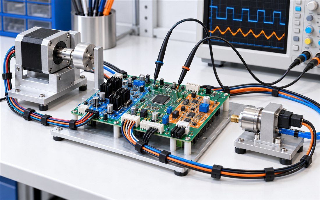
Inspect temperature and mechanical retention as well as waveforms. Verify connector engagement, motor-driver thermal paths, sensor cable strain relief, and test-point access in the assembled enclosure. Route scope probes and current clamps so the measurement setup does not create a new return or inject noise. Record each test condition and acceptance decision in the product’s risk and design history. A PCB engineering DFM review can help convert those constraints into clear fabrication and assembly notes. A PCB prototype build can confirm test access and enclosure fit on the chosen revision.
Release the configuration for repeatable builds
The production package should include the final schematic and net names, layer stack, copper weights, controlled-impedance notes where applicable, finished outline, drill and slot data, motor and sensor connector pinouts, BOM, approved alternates, assembly drawing, and inspection points. Call out polarity and orientation for current-sense devices, protection parts, connectors, and transducers. Mark any zones that must remain free of copper, adhesive, coating, or mechanical hardware.
Link every performance observation to the actual bill of materials, motor, sensor, firmware, and enclosure revision. If an alternate driver, inductor, sensor, or connector is proposed, assess its current path, thermal behavior, measurement range, timing, and test impact before approving it. A PCB prototype review helps uncover access and integration issues before the release package is frozen. For later lots, the released configuration and verified changes should be the source of truth.
In short, infusion-pump motor drive and sensing should be reviewed as neighboring current systems with different signal levels and different verification needs. Trace both loops, keep switching currents local, preserve the sensor reference, and test the assembled configuration across defined conditions. A Healthcare PCB process review can connect those decisions to panelization, assembly, inspection, and change control.
Sources: U.S. FDA, Infusion Pumps Total Product Life Cycle Guidance, for device lifecycle engineering and validation context; Texas Instruments, Step Motor Drive Techniques (SLVA767A), for example motor-drive modes and current behavior; U.S. FDA Infusion Pump Improvement Initiative, for risk-reduction and validation context. No pump performance result or device authorization is claimed for KKPCB.

