
Edge controllers in a smart factory combine field power, processors, memory, Ethernet, and I/O in an enclosure that may have little spare airflow. A board can pass a short functional test yet drift when network traffic increases, a processor runs a vision task, or a cabinet warms after several hours. A Smart Factory PCB must therefore make the power tree, thermal path, noisy return, and quiet reference visible in the same design review.
A Smart Factory PCB power review should be shared by electrical, mechanical, manufacturing, and service teams before the cabinet is frozen.
The project pain is usually cross-functional: electrical engineering owns the rails, mechanical engineering owns the heat sink, and manufacturing owns the copper and via process. If those decisions are not released together, the production board may meet each drawing separately and still create a hot spot or a reference shift in the enclosure.
- Map input protection, conversion, loads, and returns before placement.
- Keep compute heat and switching nodes away from analog and timing references.
- Use copper, vias, spreaders, and enclosure contact as one thermal path.
- Validate rails, temperature, network activity, and fit under realistic load.
Table of contents
For a Smart Factory PCB, the power tree is the map that keeps high-current and quiet-reference decisions aligned.
Map the power tree before routing signals
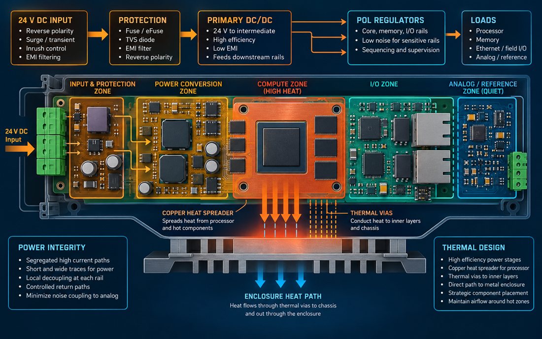
The first review of a Smart Factory PCB should draw the 24 V input, protection, primary converter, point-of-load rails, Ethernet, processor, memory, field I/O, and analog reference. Mark where each current leaves and returns. A short, wide path for the converter hot loop is more useful than a large plane that allows switching current to wander beneath the processor or clock.
The PCB materials stack determines how much copper and dielectric thickness is available for spreading heat and controlling impedance. If the design uses heavier copper or thermal vias, put those assumptions in the controlled fabrication data. A supplier cannot infer a thermal requirement from a generic layer count.
Separate noisy returns from the quiet reference
Converter and field-output returns can carry large, fast currents. Keep them out of the analog reference, sensor return, and clock supply path. A high-frequency PCB mindset helps because the return impedance changes with edge rate and via geometry, not only with DC resistance. Define the point where noisy and quiet regions meet instead of allowing a random plane overlap to make the decision.
When an Ethernet PHY or isolated I/O shares the board, show its shield and chassis relationship. A metal enclosure can provide a useful common-mode path, but only when the bond is intentional. The PCB manufacturing package should identify copper pours, via stitching, and any keep-out needed to preserve that path.
An Industrial edge Smart Factory PCB needs a continuous thermal path from component pad to enclosure contact.
Design a continuous thermal path to the enclosure
Thermal spreading starts at the component pad and ends at the enclosure or airflow path. Use copper under the hot device, thermal vias with a defined drill and fill expectation, inner-layer spread, and a mechanical interface that does not leave a gap. For a Smart Factory PCB, the heat path should be shown in the mechanical and board drawings so a coating mask or mounting bracket cannot interrupt it.
Do not place the hottest converter or processor next to the reference oscillator, precision sensor, or temperature-sensitive connector. Thermal gradients can create functional drift even when the average board temperature appears acceptable. The fabrication release should identify thermal vias, copper weight, and any exposed pad requirement that the assembly process must reproduce.
Use the enclosure as a controlled interface
A heat spreader, shield, or chassis contact may be electrically conductive. Define whether it is chassis, signal reference, or mechanical only. If a screw or spring is part of the thermal path, specify the surface and torque assumptions. A PCB assembly traveler should identify thermal interface material, standoff, fastener, and coating keep-outs so the assembler does not create a new thermal or electrical condition.
Coating can protect against humidity but can also insulate a contact or trap heat around a component. Mark clean areas around spreaders, probe points, vents, and connector shells. Select surface finish for the actual contact and corrosion environment rather than as a default selection.
The Smart Factory PCB quiet zones must remain usable when processor workload and network traffic change.
Protect timing, analog, and service references
Processor and memory activity changes with workload. Keep the oscillator, ADC reference, and sensitive sensor path away from the compute hot zone and its return. The Smart Factory PCB should include probe access, thermal camera sightlines, and the ability to inspect the quiet reference after the enclosure is installed.
Reserve test points for input, critical rails, chassis, and quiet reference. Do not place a long test stub on a high-speed net merely to make the fixture convenient. A controlled prototype PCB should be tested with the final heat spreader, enclosure, fan or airflow assumption, and network load.
A Smart Factory PCB release is meaningful only when rail, temperature, timing, and enclosure evidence are collected under realistic load.
Validate rails and temperature under real workload
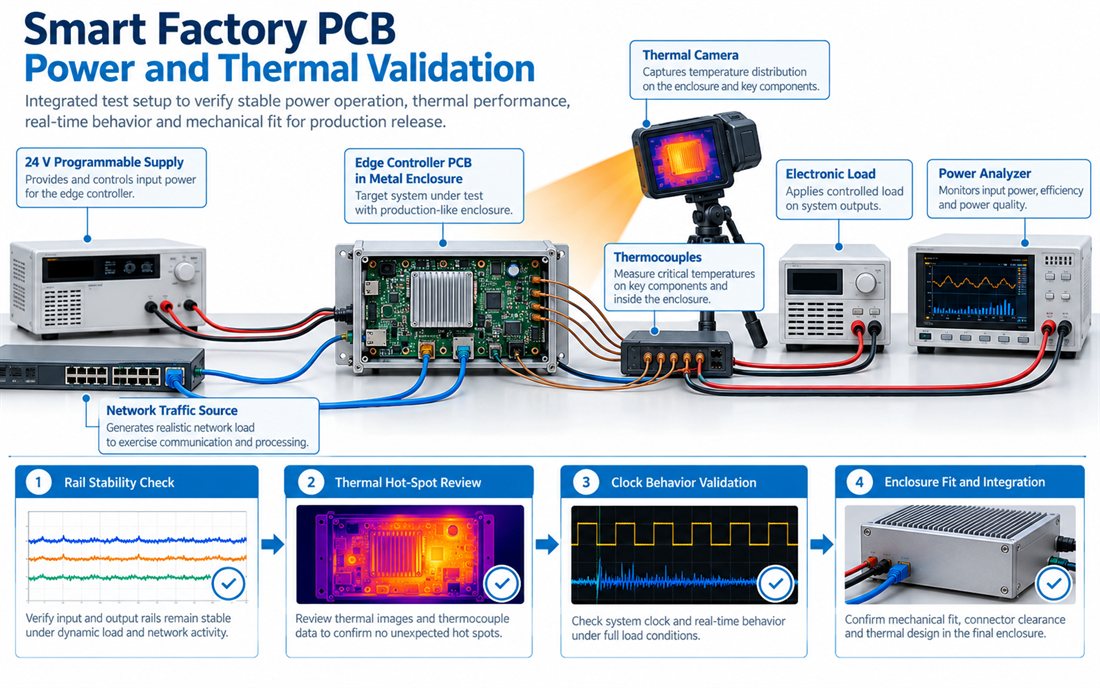
A thermal release fixture should combine programmable input power, representative network traffic, processor or I/O workload, electronic load, thermal camera or probes, and the production enclosure. Check rail stability, hot-spot location, reference behavior, connector clearance, and service access. The second illustration is a conceptual validation workflow, not a measured customer result.
Map hot spots and rail behavior to decisions
Record board revision, heat-spreader hardware, coating state, input condition, workload, traffic, and fixture wiring. The assembly fixture should carry those identifiers so a thermal result cannot be separated from the configuration that produced it.
| Check | Question | Evidence |
|---|---|---|
| Power tree | Do protection, converters, loads, and returns match the released map? | Schematic/layout review and rail record |
| Thermal path | Does heat reach the spreader and enclosure without a process gap? | Mechanical drawing and thermal inspection |
| Quiet reference | Does workload avoid moving clock, analog, or sensor references? | Workload fixture and observation record |
| Service | Can technicians probe and replace the board safely? | Enclosure fit and access check |
Freeze power and thermal assumptions before purchasing
The Smart Factory PCB purchase release should preserve the approved converters, thermal path, copper, via, and enclosure assumptions.
Before releasing the next lot of a Smart Factory PCB, freeze the power modules, copper and via requirements, heat spreader, enclosure contact, coating mask, and workload fixture. An alternate converter can change switching frequency, heat, and noise even if its input and output ratings match. Attach the approved PCB manufacturing package and material assumptions to the production release.
A Smart Factory PCB continuous-operation build is ready for continuous operation when its power, thermal, network, reference, and service evidence agree. A controlled pilot thermal build is the practical checkpoint before the cabinet is filled with production units.
The Smart Factory PCB handoff is strongest when power integrity and mechanical thermal evidence agree.
Sources: Analog Devices power, thermal, signal-chain, and clock guidance; Würth Elektronik grounding, assembly, and thermal-interface notes; Qorvo interface references; power-module, enclosure, heat-spreader, coating, and PCB material supplier application data. The diagrams are original conceptual engineering graphics and do not represent a customer measurement or qualification report.
