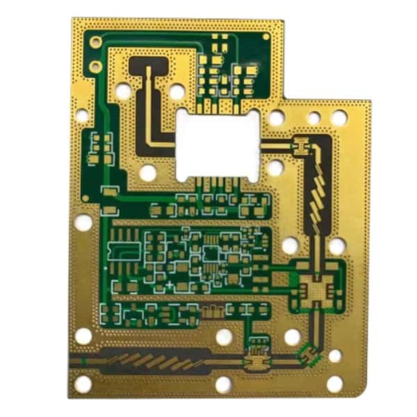
A Rogers PCB is a printed circuit board made from Rogers high-frequency laminates, engineered to provide stable dielectric constants (Dk), low dissipation factors (Df), and superior thermal performance. These features make Rogers PCBs ideal for RF, microwave, and high-speed digital circuits where signal integrity is critical.
Rogers PCBs are widely used in:
-
Wireless communication systems (5G, LTE, Wi-Fi)
-
Satellite and aerospace electronics
-
Radar and microwave modules
-
High-speed networking equipment
Their primary goal is to maintain high-frequency signal fidelity while reducing signal loss and electromagnetic interference (EMI).
Design Challenges
Designing Rogers PCBs involves addressing several key challenges:
-
High-Frequency Signal Loss: Dielectric and conductor losses can degrade signals at GHz frequencies.
-
Impedance Control: Inconsistent trace widths or substrate variations can cause reflections and signal distortion.
-
Crosstalk and EMI: Dense routing increases the potential for interference between adjacent traces.
-
Thermal Management: High-frequency operation and tightly packed components generate heat that may affect Dk stability.
-
Manufacturing Tolerances: Minor deviations in etching, lamination, or via alignment can negatively impact high-frequency performance.
Engineering Solutions
Engineers implement a variety of strategies to optimize Rogers PCBs:
-
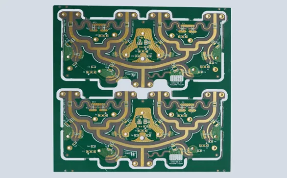
Controlled Impedance Traces: Microstrip, stripline, and coplanar waveguides are designed to precise impedance to reduce reflection and maintain signal integrity.
-
Trace Optimization: Smooth bends and gradual transitions minimize signal distortion and insertion loss.
-
Differential Pairs and Shielding: Differential routing and guard traces reduce EMI and improve noise immunity.
-
Layer Stack-Up Planning: Separating RF signals from power planes and noisy layers reduces crosstalk.
-
Thermal Management: Copper pours, thermal vias, and heat-spreading designs mitigate hotspots and maintain consistent Dk.
Material & Fabrication Considerations
Rogers PCBs require specialized materials and precision fabrication techniques:
-
Rogers Laminates: Low-loss, high-frequency laminates such as RO4000, RO3000, and RO4350B provide stable Dk and minimal signal attenuation.
-
High-Precision Drilling & Plating: Microvias and through-holes are carefully manufactured to prevent impedance discontinuities.
-
Surface Finishes: ENIG, hard gold, or immersion silver improve solderability and maintain RF performance.
-
Quality Assurance:
-
Impedance testing and Vector Network Analysis (VNA) for insertion and return loss
-
AOI and X-ray inspections verify trace and via integrity
-
Thermal cycling tests confirm stability under operational conditions
-
KKPCB applies rigorous QA processes to deliver Rogers PCBs that consistently meet high-frequency performance requirements.
Applications
Rogers PCBs are essential for high-frequency and high-performance electronics:
-
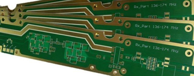
Wireless Communication: RF front-end modules, antennas, and 5G base stations
-
Satellite & Aerospace Systems: Radar modules, transceivers, and communication circuits
-
Microwave Devices: Amplifiers, filters, and mixers operating at GHz frequencies
-
High-Speed Networking: Routers, switches, and high-frequency data transmission boards
-
Test & Measurement Equipment: Precision RF diagnostic and measurement instruments
By integrating advanced Rogers laminates, precise trace design, controlled impedance, and strict QA, KKPCB delivers Rogers PCBs capable of maintaining signal integrity, low loss, and reliable performance in high-frequency electronic systems.
