
The Role of RF Amplifiers in Modern Electronics
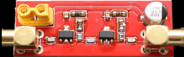
In modern RF and microwave systems, RF amplifiers are essential components that boost signal strength to ensure reliable transmission and reception.
They are widely used in:
- 5G/6G communication systems
- Wireless modules and IoT devices
- Radar systems
- Satellite communication
- Broadcasting equipment
For PCB electronics manufacturers, understanding RF amplifiers is critical for achieving high-performance PCB design, signal integrity, and low-loss transmission.
At KKPCB, RF amplifier PCB design is optimized for low loss, stable gain, and high-frequency reliability.
2. What Is an RF Amplifier?
An RF amplifier is an electronic device that increases the amplitude of radio frequency signals without significantly distorting them.
Key functions:
- Signal amplification
- Power boosting
- Noise minimization
RF amplifiers operate across frequencies ranging from MHz to GHz and mmWave bands.
3. Types of RF Amplifiers
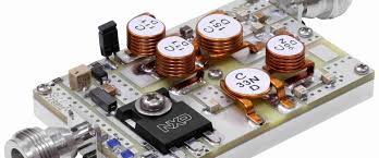
3.1 Low Noise Amplifier (LNA)
- Used at receiver front-end
- Amplifies weak signals
- Minimizes noise figure
3.2 Power Amplifier (PA)
- Boosts signal power for transmission
- Used in transmitters
3.3 Driver Amplifier
- Intermediate stage between LNA and PA
- Provides sufficient drive level
3.4 Broadband vs Narrowband Amplifiers
- Broadband: wide frequency range
- Narrowband: optimized for specific frequency
4. Key RF Amplifier Parameters
4.1 Gain
Gain represents amplification level:G = Pₒᵤₜ / Pᵢₙ
Higher gain improves signal strength but must be balanced with stability.
4.2 Noise Figure (NF)
- Indicates noise introduced by amplifier
- Critical for LNA performance
4.3 Linearity
- Ability to amplify without distortion
- Important for high data-rate systems
4.4 Efficiency
- Ratio of RF output power to DC input power
- Critical for power amplifiers
5. Impedance Matching in RF Amplifier PCB Design
Proper impedance matching is essential for maximum power transfer:
Zin=ZoutZ_{in} = Z_{out}Zin=Zout
Mismatch can cause:
- Signal reflection
- Power loss
- Reduced efficiency
Matching techniques:
- Microstrip lines
- Lumped components (L, C networks)
- Smith chart optimization
6. PCB Design Considerations for RF Amplifiers
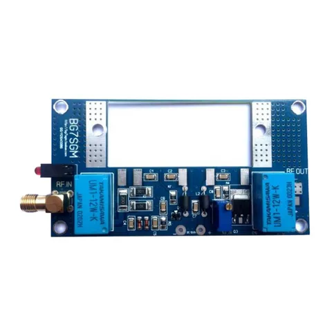
6.1 High-Frequency PCB Material Selection
Use low-loss materials:
- Rogers (RO4350B, RO4835)
- PTFE-based laminates
Benefits:
- Reduced insertion loss
- Stable dielectric properties
6.2 Controlled Impedance Routing
- Maintain consistent transmission line impedance
- Use precise trace width and spacing
6.3 Grounding and Shielding
- Solid ground planes
- RF shielding structures
- Minimized return path impedance
6.4 Layout Optimization
- Short RF signal paths
- Avoid sharp bends
- Isolate RF from digital circuits
7. Thermal Management in RF Amplifier PCB
Power amplifiers generate heat.
Thermal design techniques:
- Thermal vias under components
- Heat sinks
- High thermal conductivity substrates
Proper thermal management ensures:
- Stable gain performance
- Longer component lifespan
8. Stability and Oscillation Prevention
RF amplifiers can become unstable.
Prevention methods:
- Proper grounding
- Isolation between stages
- Feedback network optimization
9. Applications of RF Amplifiers
RF amplifiers are used in:
- 5G base stations
- Wireless communication modules
- Automotive radar systems
- Satellite communication
- IoT devices
10. KKPCB RF Amplifier PCB Capability
At KKPCB, capabilities include:
- Low-loss RF PCB fabrication
- Controlled impedance design
- RF signal integrity optimization
- Thermal and EMI design support
- High-frequency testing and validation
This ensures:
- Stable RF amplification
- High efficiency and reliability
- Scalable production
11. Conclusion
RF amplifiers are fundamental to modern RF and microwave systems, enabling reliable signal transmission and reception.
For PCB manufacturers, understanding RF amplifier design is essential for optimizing:
- Signal integrity
- Impedance matching
- Thermal performance
- EMI control
With advanced RF engineering expertise, KKPCB delivers high-performance PCB solutions for RF amplifier applications.

