
With the rapid expansion of 5G networks, high-capacity wireless communication, and advanced antenna systems, base stations require increasingly sophisticated RF solutions to achieve higher data throughput, wider coverage, and improved spectral efficiency.
Massive MIMO (Multiple Input Multiple Output) technology is a key architecture in 5G base stations. By integrating multiple transmitting and receiving channels, Massive MIMO systems can significantly improve:
- Network capacity
- Signal coverage
- User connection density
- Communication reliability
However, as the number of antenna channels increases, RF PCB design becomes increasingly challenging. A 16T16R Massive MIMO antenna array PCB requires precise control of:
- RF signal integrity
- Channel isolation
- Phase consistency
- Impedance matching
- Thermal performance
- Manufacturing accuracy
This case study presents how KKPCB supported the development of a high-isolation 16T16R Massive MIMO antenna array PCB solution, helping improve RF performance, production reliability, and system integration capability for 5G base station applications.
1. Project Background
A customer developing a 5G base station antenna module required a customized RF PCB solution for a 16-transmit and 16-receive (16T16R) Massive MIMO system.
The antenna array PCB needed to integrate multiple RF channels within a limited physical area while maintaining stable electrical performance.
The product requirements included:
- 16 independent RF transmitting channels
- 16 receiving channels
- High channel-to-channel isolation
- Low signal loss
- Stable phase performance
- Long-term outdoor operation reliability
During prototype development, the customer encountered several RF PCB challenges related to interference control, signal consistency, and manufacturing feasibility.
2. Key Challenges in 16T16R Massive MIMO PCB Development
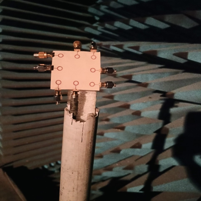
Challenge 1: High Channel Isolation Between RF Paths
Customer Pain Point
Massive MIMO antenna systems contain many closely positioned RF channels.
Insufficient isolation between channels may cause:
- Crosstalk
- Signal distortion
- Reduced beamforming accuracy
- Lower system capacity
The PCB design needed to control electromagnetic coupling between:
- Transmit channels
- Receive channels
- Antenna feeding networks
Challenge 2: RF Signal Integrity and Loss Control
Customer Pain Point
5G communication systems operate at high frequencies, where PCB material and routing structures directly affect RF performance.
Potential issues included:
- Increased insertion loss
- Impedance mismatch
- Phase variation
- Signal attenuation
The PCB required optimized control of:
- Transmission line geometry
- Dielectric material selection
- Stack-up structure
Challenge 3: Multi-Channel Phase Consistency
Customer Pain Point
Massive MIMO relies on precise phase control for beamforming.
Small differences between RF paths may affect:
- Beam direction accuracy
- Coverage performance
- Signal quality
The PCB design needed to maintain:
- Consistent electrical length
- Stable dielectric properties
- Controlled manufacturing tolerance
Challenge 4: Thermal Management in High-Density RF Systems
Customer Pain Point
5G base station antenna modules operate continuously outdoors.
Heat sources include:
- RF power amplifiers
- Active components
- Power management circuits
Poor thermal management may result in:
- Performance degradation
- Component aging
- Reduced reliability
Challenge 5: Manufacturing Complexity and Reliability
Customer Pain Point
The antenna array PCB required:
- Fine RF structures
- High layer count
- Tight impedance control
- Precise registration accuracy
Manufacturing challenges included:
- Layer alignment
- Copper thickness consistency
- Surface finish quality
- Process repeatability
3. KKPCB Engineering Support and Solutions
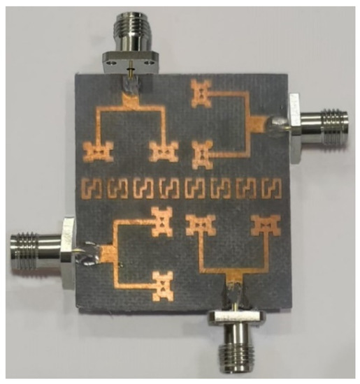
3.1 RF PCB Stack-Up Optimization
KKPCB engineering team reviewed the RF PCB structure and optimized:
- Layer arrangement
- Signal/reference plane configuration
- Dielectric material selection
The design focused on:
- Stable impedance performance
- Reduced signal loss
- Improved RF consistency
Suitable high-frequency materials were considered based on:
- Frequency range
- Loss requirements
- Thermal conditions
3.2 High-Isolation RF Layout Optimization
To improve channel isolation, the engineering team optimized:
RF Channel Routing
Improvements included:
- Increased spacing between sensitive RF paths
- Optimized routing direction
- Reduced parallel coupling areas
Grounding and Shielding Design
The design enhanced:
- Ground plane continuity
- RF return paths
- Isolation structures
These improvements helped reduce:
- Electromagnetic coupling
- Crosstalk interference
- Channel interaction
3.3 Impedance Control and Signal Integrity Improvement
For high-frequency RF transmission lines, KKPCB optimized:
- Trace width
- Trace spacing
- Dielectric thickness
- Copper thickness
Manufacturing controls included:
- Stack-up verification
- TDR impedance testing
- Process parameter control
This improved:
- RF signal consistency
- Insertion loss performance
- Production repeatability
3.4 Phase Consistency Optimization
To support Massive MIMO beamforming performance, PCB design focused on:
- Matched RF paths
- Controlled electrical lengths
- Stable material characteristics
This helped maintain consistent RF behavior across multiple channels.
3.5 Thermal Management Optimization
For continuous base station operation, thermal design considered:
- High-power component placement
- Copper distribution
- Heat dissipation paths
- Mechanical integration requirements
The optimization improved:
- Thermal stability
- System lifetime
- Outdoor reliability
3.6 Manufacturing Process Optimization
To support production requirements, KKPCB provided:
- RF PCB fabrication support
- Process optimization
- Quality inspection
Manufacturing control included:
- AOI inspection
- X-ray inspection where required
- Impedance testing
- Electrical verification
4. Manufacturing and Quality Control Process
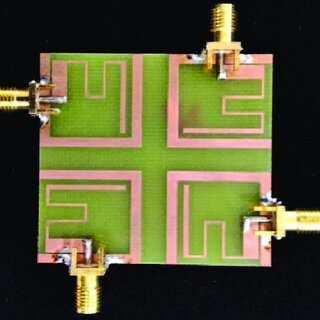
RF PCB Fabrication
The 16T16R Massive MIMO PCB required strict manufacturing control.
Key considerations included:
- High-frequency laminate processing
- Multilayer alignment
- Controlled impedance fabrication
- Surface finish consistency
PCB Material Selection
Depending on RF requirements, materials may include:
- Rogers high-frequency laminates
- Low-loss RF materials
- Hybrid RF/FR-4 stack-up structures
Material selection considered:
- Dielectric constant stability
- Dissipation factor
- Thermal reliability
Inspection and Testing
Quality verification included:
AOI Inspection
Checking:
- PCB pattern defects
- Manufacturing consistency
TDR Impedance Testing
Verification of:
- RF transmission line impedance
- Process stability
Electrical Testing
Including:
- Continuity testing
- Isolation testing
RF Performance Validation
Testing parameters included:
- Insertion loss
- Return loss
- Channel isolation
- Signal consistency
5. Project Results
Through RF PCB design optimization and manufacturing process improvements, the project achieved:
- Improved channel isolation performance
- Enhanced RF signal stability
- Improved phase consistency
- Better production repeatability
Validation results included:
- Channel isolation improved by more than 15 dB
- RF impedance control within ±5% tolerance
- 98%+ first-pass production yield
- Reduced RF debugging time during system integration
6. Key Engineering Insights
6.1 Massive MIMO Performance Depends on PCB-Level RF Control
A high-performance antenna system requires more than advanced RF chips.
PCB design directly influences:
- Signal integrity
- Channel isolation
- Beamforming accuracy
- System efficiency
6.2 Material Selection Is Critical for 5G RF Applications
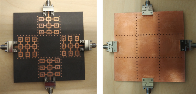
At high frequencies, PCB materials affect:
- Signal loss
- Phase stability
- Thermal behavior
Selecting the correct laminate is essential for maintaining RF performance.
6.3 Manufacturing Capability Determines RF Reliability
High-frequency PCB performance depends heavily on manufacturing consistency.
Important factors include:
- Stack-up accuracy
- Impedance control
- Registration precision
- Surface finish quality
7. Applications of Similar RF PCB Solutions
Customized RF PCB solutions can support:
5G Base Stations
Applications:
- Massive MIMO antenna modules
- Active antenna units
Wireless Communication Equipment
Applications:
- RF front-end modules
- High-frequency communication systems
Satellite and Aerospace Communication
Applications:
- High-frequency communication terminals
- RF control systems
Radar and Sensing Systems
Applications:
- Automotive radar
- Industrial radar equipment
Conclusion
The development of a high-isolation 16T16R Massive MIMO antenna array PCB requires advanced RF engineering capability and precise manufacturing control.
In this project, KKPCB supported the customer through:
- RF stack-up optimization
- High-isolation layout design
- Impedance control
- Phase consistency improvement
- Thermal management optimization
- Manufacturing process control
The solution helped transform a complex 5G antenna PCB design into a reliable and production-ready RF platform.
As wireless communication systems continue moving toward higher frequencies, larger antenna arrays, and greater integration density, advanced RF PCB solutions will remain a critical foundation for next-generation communication infrastructure.
