
With the rapid development of industrial automation, electric mobility, energy storage systems, and backup power applications, industrial battery chargers have become critical components for ensuring stable and reliable power supply.
Unlike consumer charging products, industrial battery chargers must operate under more demanding conditions, requiring:
- High charging efficiency
- Stable power conversion
- Accurate battery management
- Long-term continuous operation
- Strong protection capability
The PCBA (Printed Circuit Board Assembly) serves as the core control platform of industrial battery chargers, integrating:
- Power conversion control
- Charging management
- Voltage and current monitoring
- Protection circuits
- Communication interfaces
This case study presents how KKPCB supported the development of an industrial battery charger PCBA solution, addressing challenges related to power reliability, thermal performance, protection design, and manufacturing readiness.
1. Project Background
A customer developing an industrial battery charging system required a customized PCBA solution for use in industrial equipment and energy backup applications.
The charger needed to support different battery operating conditions while maintaining stable charging performance.
The product requirements included:
- High-efficiency power conversion
- Accurate voltage and current regulation
- Continuous operation capability
- Compact design
- Reliable protection functions
During the transition from prototype development to production, the customer identified several PCB-level challenges affecting system stability and manufacturing consistency.
2. Key Challenges in Industrial Battery Charger PCBA Development
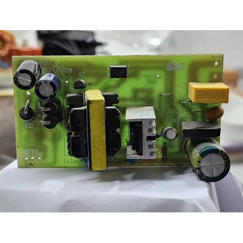
Challenge 1: High-Power Circuit Reliability
Customer Pain Point
Industrial battery chargers typically operate with higher power levels compared with consumer charging devices.
The PCBA needed to handle:
- High input voltage
- High charging current
- Continuous power operation
Potential risks included:
- Excessive temperature rise
- Voltage drop
- Component stress
- Reduced service life
The design required optimized:
- Power routing
- Copper thickness
- Component selection
- Thermal paths
Challenge 2: Power Conversion Efficiency
Customer Pain Point
The charger required efficient energy conversion to reduce:
- Power losses
- Heat generation
- Operating costs
The power stage involved components such as:
- MOSFETs
- Diodes
- Transformers
- Inductors
- Capacitors
PCB design needed to optimize:
- Switching loops
- Current return paths
- Component placement
Challenge 3: Thermal Management During Continuous Operation
Customer Pain Point
Industrial chargers often operate for extended periods.
Heat accumulation could affect:
- Charging efficiency
- Component reliability
- System lifetime
Thermal challenges included:
- Power semiconductor heating
- Transformer temperature rise
- Uneven heat distribution
Challenge 4: Protection and Safety Design
Customer Pain Point
Battery charging systems must prevent abnormal operating conditions.
The PCBA required protection against:
- Overvoltage
- Overcurrent
- Short circuit
- Reverse connection
- Overtemperature
Reliable protection design was essential to prevent equipment damage and improve operational safety.
Challenge 5: Communication and Monitoring Integration
Customer Pain Point
Modern industrial chargers often require communication with:
- Battery management systems (BMS)
- Industrial controllers
- Monitoring platforms
Common interfaces include:
- CAN bus
- RS-485
- Modbus
The PCBA needed to ensure:
- Stable data transmission
- Noise resistance
- Interface protection
3. KKPCB Engineering Support and Solutions
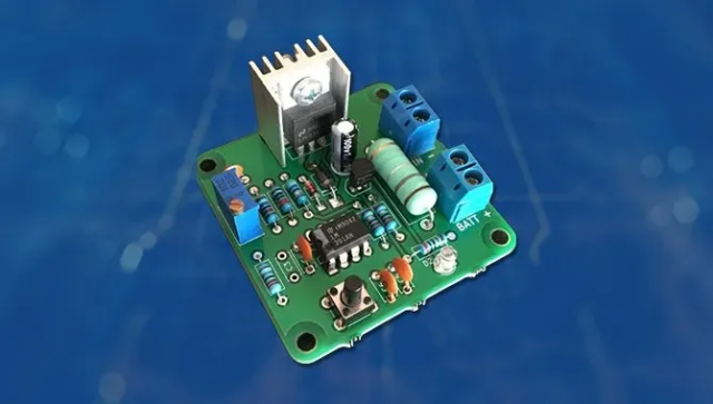
3.1 Power PCB Design Review and DFM Analysis
Before manufacturing, KKPCB engineering team performed a comprehensive review focusing on:
- Power circuit layout
- Component placement
- Thermal design
- Manufacturing feasibility
The review helped identify potential risks related to:
- High-current routing
- Assembly reliability
- Testing accessibility
Optimization suggestions improved production readiness.
3.2 High-Current PCB Layout Optimization
To improve power handling capability, the engineering team optimized:
Power Trace Design
Considerations included:
- Trace width
- Copper thickness
- Current density
Power Loop Optimization
The design reduced:
- Unnecessary current loops
- Parasitic inductance
- Switching interference
Benefits included:
- Lower power loss
- Improved conversion efficiency
- Better electrical stability
3.3 Thermal Management Improvement
The PCBA design was optimized through:
- Heat-generating component placement
- Larger copper areas
- Thermal via design
- Improved heat dissipation paths
These improvements helped maintain:
- Stable charging performance
- Longer component lifetime
- Better reliability under continuous operation
3.4 Protection Circuit Optimization
The protection system was enhanced through:
- Overcurrent protection design
- Surge protection
- Voltage monitoring circuits
- Temperature detection
These functions improved:
- System safety
- Fault response capability
- Product reliability
3.5 Communication Interface Optimization
For intelligent charging systems, PCB design improvements included:
- Signal routing optimization
- Isolation design
- Noise filtering
This supported reliable communication between:
- Charger controller
- Battery management system
- External monitoring equipment
4. Manufacturing and Quality Control Process
PCB Fabrication
Industrial battery charger PCBAs require strict manufacturing control.
Key considerations included:
- Multilayer PCB structure
- High-Tg FR-4 material
- Copper thickness selection
- Electrical isolation requirements
Manufacturing quality control focused on:
- Layer alignment
- Copper consistency
- Hole reliability
SMT and THT Assembly
Industrial chargers often combine:
SMT Components
Used for:
- Control ICs
- Driver circuits
- Sensing circuits
Through-Hole Components
Used for:
- Power connectors
- Large capacitors
- Transformers
- Inductors
Advantages:
- Strong mechanical reliability
- Better current handling capability
Inspection and Testing
Quality control included:
SPI Inspection
Ensures:
- Solder paste accuracy
- Printing consistency
AOI Inspection
Checks:
- Component placement
- Solder defects
X-Ray Inspection
Used for:
- Hidden solder joints
- Complex power connections
Functional Testing
Verification included:
- Output voltage accuracy
- Charging current control
- Protection functions
- Communication performance
5. PCB Technologies for Industrial Battery Chargers
5.1 Multilayer PCB
Advantages:
- Improved power distribution
- Better signal isolation
- Higher circuit density
Applications:
- Intelligent charging controllers
5.2 Heavy Copper PCB
Advantages:
- Higher current capacity
- Better thermal performance
Applications:
- High-power charging systems
5.3 High-Tg PCB
Advantages:
- Better thermal stability
- Improved reliability under temperature cycling
Applications:
- Industrial environments
5.4 Metal Core PCB
Advantages:
- Enhanced heat dissipation
Applications:
- High-power charging modules
6. Applications of Industrial Battery Charger PCBAs
Industrial Equipment
Applications:
- Factory automation equipment
- Material handling systems
- Industrial machinery
Requirements:
- Continuous operation
- High reliability
Energy Storage Systems
Applications:
- Battery backup systems
- Energy management equipment
Requirements:
- Stable charging control
- Safety protection
Electric Vehicles and AGV Systems
Applications:
- Automated guided vehicles
- Industrial mobile robots
Requirements:
- Efficient charging
- Communication with BMS
Renewable Energy Applications
Applications:
- Solar energy storage
- Off-grid power systems
Requirements:
- Reliable energy conversion
7. Project Results
Through PCB design optimization and manufacturing process improvement, the industrial battery charger PCBA achieved:
- Improved power conversion stability
- Enhanced thermal performance
- Improved protection reliability
- Better production consistency
Validation results included:
- 98%+ first-pass production yield
- Reduced debugging time during production ramp-up
- Improved long-term operational reliability
8. Key Engineering Insights
8.1 Power PCB Design Determines System Reliability
For industrial battery chargers, PCB design directly affects:
- Efficiency
- Thermal performance
- Electrical stability
A reliable solution requires optimization of:
- Power paths
- Switching loops
- Heat dissipation
8.2 Protection Design Is Essential for Battery Systems
Battery charging applications require comprehensive protection against abnormal conditions.
PCB-level considerations include:
- Current monitoring
- Voltage sensing
- Isolation
- Fault response
8.3 Manufacturing Readiness Should Be Considered Early
A successful prototype does not always guarantee smooth mass production.
Early DFM review helps identify:
- Assembly risks
- Testing challenges
- Reliability issues
before production scaling.
Conclusion
Industrial battery charger PCBAs are critical components that support reliable energy management in modern industrial systems.
A successful solution requires comprehensive consideration of:
- High-current power design
- Thermal management
- Protection circuits
- Communication reliability
- Manufacturing feasibility
In this case, KKPCB supported the customer through power PCB optimization, DFM analysis, thermal improvement, and production process control, helping transform a battery charger design into a reliable and manufacturable industrial solution.
As industrial electrification and energy storage technologies continue expanding, customized PCBA solutions will play an increasingly important role in improving charging efficiency, safety, and system reliability.
