
High-mix automation equipment rarely stays unchanged after the first pilot. A controller gains a new sensor, a terminal block is substituted, firmware changes the diagnostic map, or a supplier proposes an equivalent protection part. The risk is not the change itself; it is losing the relationship between the released BOM, layout, test fixture, and machine configuration. An Industrial Automation PCB needs a change-control package that lets engineering, purchasing, manufacturing, and service teams identify exactly what is still compatible.
An Industrial Automation PCB change review should identify the exact board, configuration, fixture, and supplier package before a new lot is authorized.
This article addresses the handoff problem behind many repeat-build escapes. It does not claim a customer project or measured result. Instead, it shows how to make a production release auditable when the design has multiple approved alternates, different machine configurations, and a long service life.
- Give the board, BOM, firmware, and test fixture one release identity.
- Review alternates by footprint, thermal, isolation, and software behavior—not only rating.
- Make DFM and test-point decisions visible in the supplier handoff.
- Close deviations before a pilot is treated as a production baseline.
Table of contents
For an Industrial Automation PCB, one release identity prevents a hardware change from becoming an undocumented service change.
Build one release identity for hardware and configuration
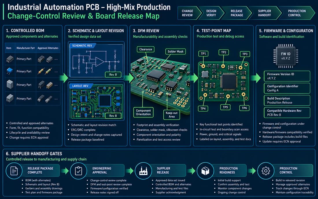
The first control for an Industrial Automation PCB is a release identifier that follows the schematic, layout, fabrication data, assembly drawing, BOM, firmware build, and configuration record. A board revision printed on the silkscreen is helpful, but it is not enough if the test fixture or machine parameter file still points to an earlier channel map. The Industrial Automation PCB and stack assumptions should be part of the same baseline when they affect thermal, dielectric, or assembly behavior.
Use a release matrix that names the controlled files, owner, approval state, and effective date. If a drawing is revised without changing the electrical function, record that relationship instead of silently creating a new production identity. Project managers can then distinguish a documentation correction from a change that requires a new pilot.
Link the test-point map to the machine function
Test points should be named by function, not only by net. A point called 24V_AUX does not tell a service technician whether it belongs to the sensor branch, relay branch, or isolated converter. The PCB manufacturing and assembly data should carry the same identifiers used in the functional test script. When a point moves, the change review can ask whether the fixture, firmware diagnostic, and wiring document also need revision.
Keep test access clear of coating, heat spreaders, and enclosure supports. A test point hidden under a bracket is not a production test point. A controlled PCB assembly drawing can show probe direction, fixture clearance, and the no-touch areas that matter during service.
An Industrial Automation PCB alternate must be checked against geometry, assembly, thermal, isolation, and machine behavior.
Evaluate alternates beyond the datasheet rating
An approved alternate may share voltage and current ratings but still change the board. Package height can collide with the enclosure; a different pad pattern can move a sensitive node; thermal resistance can change a local threshold; a relay contact material can affect service life. The high-frequency PCB review habit of checking geometry and return path is useful even on a control board because fast switching and cable coupling depend on physical placement.
For every alternate, compare footprint, pinout, creepage, clearance, thermal pad, solder profile, supply chain, and firmware assumptions. Mark which items are equivalent and which require a verification build. Do not let a buyer approve an alternate from a PDF rating table while the engineer is still assuming the original package.
Protect materials and finishing assumptions
Board material, copper weight, surface finish, solder mask, and coating can change the manufacturing window. A fabrication release should identify which values are design requirements and which are supplier capabilities. If an alternate component changes the local heat load, confirm that copper spreading, thermal vias, and assembly profile still make sense.
The surface finish and exposed contact areas also belong in the substitution review. A connector that mates with a different plating system or a terminal that sees a harsher environment may need a new corrosion or retention check. Keeping these assumptions in the release matrix prevents them from being lost in a purchasing email.
The Industrial Automation PCB supplier handoff is where design intent becomes a buildable and testable data set.
Connect DFM decisions to the supplier handoff
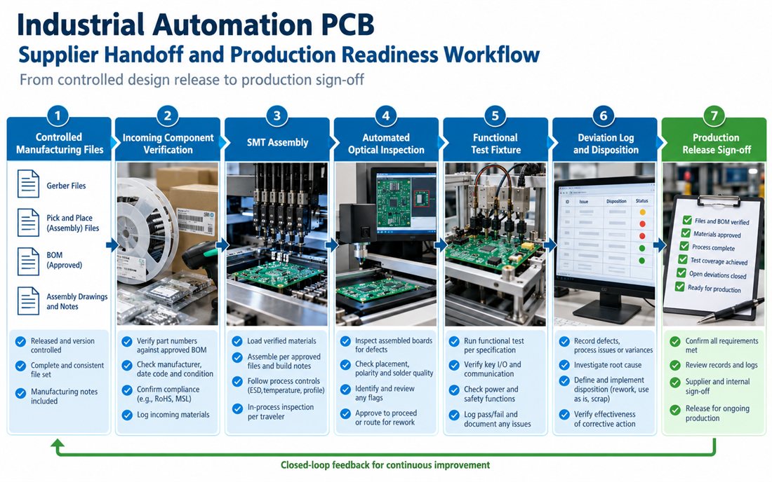
A supplier should receive a complete package: released Gerbers or ODB++ data, drill and stack information, pick-and-place, BOM with approved alternates, assembly drawing, coating mask, test-point map, inspection criteria, and deviation status. The Industrial Automation PCB should confirm that the package can be built and tested as written. It should also identify what is not included so an assumption does not become an undocumented process step.
Ask the supplier to acknowledge revision, file completeness, material, finish, and special process requirements. For a high-mix line, a short supplier release acknowledgement is often more valuable than a long generic capability statement because it connects the specific release to the process. If the supplier proposes a process change, route it through the same engineering change record as a component alternate.
Use the pilot to close the unknowns
A pilot build should answer bounded questions: does the connector fit, can the fixture probe the selected test points, does the coating mask leave the service contacts clear, and does the alternate component assemble with the approved profile? A prototype PCB is not a production waiver. Record each open item with an owner, evidence required, and closure decision before the pilot is promoted to a baseline.
Keep deviations visible. A board may function while a mechanical or documentation deviation remains open. The release owner should decide whether the issue is accepted for this build, corrected before the next lot, or escalated to a design revision. This prevents a temporary workaround from becoming the unofficial standard.
An Industrial Automation PCB release is not closed until service, firmware, test, and deviation records identify the same hardware.
Close the change loop with evidence that survives service
Production readiness includes service. Store the board revision, firmware/configuration identifier, approved alternates, test fixture revision, and deviation disposition together. When a field technician replaces a board, the service document should identify the compatible hardware and configuration rather than relying on a visual match. The assembly fixture and functional test record should use the same release identifier so a reworked board cannot be mistaken for an earlier build.
Make the release review a short, repeatable meeting
A focused release review can ask six questions: Are files complete? Are material and finish assumptions approved? Are alternates compatible? Can the board be built and inspected? Can the fixture test the intended functions? Are deviations closed or explicitly accepted? The questions are simple, but they force engineering, purchasing, manufacturing, and quality to look at the same evidence.
| Decision | Owner evidence | Release action |
|---|---|---|
| Alternate accepted | Footprint, pinout, thermal, and process comparison | Add to controlled BOM |
| DFM issue closed | Supplier response and corrected data | Update release package |
| Test coverage complete | Fixture revision and functional record | Approve pilot or production |
| Deviation remains | Risk owner and expiry or correction plan | Hold, accept, or issue ECN |
Freeze the production contract before the next purchase order
The Industrial Automation PCB purchase release should preserve the approved alternates, files, test points, and configuration identifier.
Before releasing the next lot of an Industrial Automation PCB, freeze the board revision, controlled BOM, approved alternates, test-point map, firmware/configuration identifier, and supplier acknowledgement. Attach the approved PCB manufacturing package and material assumptions so purchasing can act without creating a second, unofficial configuration.
An Industrial Automation PCB high-mix build is ready for high-mix production when a change can be traced from the reason for change to the physical board, process step, test result, and service instruction. A controlled pilot release is the final opportunity to close unknowns before they become field work.
The Industrial Automation PCB handoff is strongest when every change has an owner, evidence, and effective revision.
Sources: Würth Elektronik manufacturing and assembly guidance; Analog Devices industrial control and interface references; Qorvo signal-integrity and protection notes; component, coating, connector, and PCB material supplier application data. The diagrams are original conceptual engineering graphics and do not represent a customer measurement or qualification report.
