
Industrial control boards often pass electrical inspection and still fail in the field because the panelization, mounting, and coating decisions were made independently. A depanelization nick becomes a vibration crack, a support post presses against a component, or selective coating reaches a connector that must remain serviceable. An Industrial Automation PCB for a machine cabinet needs a production design that survives handling, fasteners, temperature changes, and repeated maintenance—not only a clean schematic.
An Industrial Automation PCB panel review should connect the board edge, support hardware, coating mask, and enclosure datum before fabrication is released.
This article shows how to connect panel DFM with mechanical reliability. It is written for teams moving from prototype to repeat builds, where the expensive question is not whether a board can be fabricated once, but whether every panel, coating boundary, connector, and support point will behave consistently.
- Place rails, fiducials, breakaway features, and mounting holes before dense routing.
- Support heavy parts without transferring vibration into fragile solder joints.
- Keep coating, heat spreading, and connector service areas intentional.
- Use a combined production and environmental release record.
Table of contents
For an Industrial Automation PCB, the panel is part of the manufacturing process and must be reviewed with the machine interface.
Plan the panel around the machine, not only the router
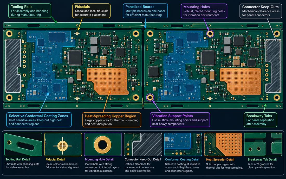
The first review of an Industrial Automation PCB panel should identify the board edge, mounting holes, connector clearance, rails, fiducials, and breakaway method. A rail that interferes with a terminal or a V-groove that runs through a high-stress corner can create damage before assembly begins. The panel drawing should show the handling direction and the location where operators or tooling may touch the board.
Use global and local fiducials that the placement machine can see after copper, solder mask, and coating keep-outs are applied. If a board has a large copper region, balance the panel so the assembly process does not introduce unnecessary bow or twist. The PCB materials stack, copper distribution, and board thickness should be considered with the fabricator before the panel shape is frozen.
Protect edges, holes, and connectors during depanelization
Score lines and routed tabs should stay away from brittle ceramic parts, high-current copper transitions, and connector mounting hardware. A PCB manufacturing partner can recommend a process window, but the product team must still decide how much edge damage is acceptable and how it will be inspected. Add a visual criterion for burrs, lifted pads, and exposed copper near a conductive enclosure.
Mounting holes deserve the same attention. A plated hole used for a ground bond, a press-fit spacer, or a vibration support has a different function from a tooling hole. Call out the finish, annular ring, and hardware interface in the drawing. Do not allow a panel rail or breakaway tab to change the hole datum that the cabinet supplier uses.
An Industrial Automation PCB survives vibration when mass, support, copper spreading, and connector retention are designed together.
Support heavy components and preserve thermal paths
Transformers, terminal blocks, relays, heat sinks, and large connectors create local mass. Under vibration, the solder joint sees a force that is not represented by a static board drawing. Put support posts or brackets near the component’s center of mass and keep them away from sensitive copper or coating keep-outs. The PCB assembly traveler should identify torque, support hardware, and any adhesive or staking process that is part of the mechanical design.
Thermal spreading and vibration support can conflict. A large copper region may need thermal vias, while a support post needs a clean mechanical land. Keep both visible in the layer and assembly data. A high-frequency PCB layout habit—short return paths and controlled reference transitions—also helps when a switching converter sits near a mechanically supported power device.
Do not let the fastener become an unplanned circuit
A metal screw or standoff can couple to a power plane, compress a coating edge, or bridge a keep-out when the board flexes. Place a mechanical exclusion around each fastener and identify whether the hardware is chassis-connected, floating, or intentionally insulated. The fabrication release should include the hole and copper clearance that the assembly hardware actually requires.
When a heat spreader is bonded to the enclosure, show its electrical relationship to the board. If it is part of a shield or protective-earth path, provide a controlled contact. If it must remain isolated, keep coating and surface finish from creating an accidental bridge. These decisions are easier to verify before a panelized prototype is assembled.
The Industrial Automation PCB coating boundary is both an electrical keep-out and a service interface.
Treat selective coating as a mechanical and electrical interface
Selective conformal coating can protect a board in dust, humidity, and chemical exposure, but it changes the rework and service envelope. On an Industrial Automation PCB, mark clean zones around connectors, test points, thermal pads, shield springs, and adjustment components. Give the assembler a mask drawing with a physical datum and a measurable boundary; a generic note such as keep connector clear is not enough.
The coating edge should not sit on a high-stress solder joint or a board breakaway feature. Meniscus, cure shrinkage, and rework can turn a small edge defect into a crack path. The surface finish, flux-cleaning process, and coating chemistry must be considered together, especially when a metal contact will be inserted or repaired repeatedly.
Keep service access after the board is mounted
Industrial technicians need to see channel labels, probe points, and connector latches after the board is installed. Reserve a service corridor and identify which fasteners can be removed without stressing the board. A Industrial Automation PCB should include a physical access check using the enclosure model, not only a clearance rule in the CAD library.
If a board is reworked, define how coating is removed and restored, how the affected area is inspected, and how the repair is recorded. A coating process that looks clean in a sample may still hide a lifted pad or a cracked solder joint. The inspection method must match the function of the covered area.
An Industrial Automation PCB reliability release is meaningful only when the fixture reproduces the enclosure and panel conditions.
Release reliability evidence that maps to real failure modes
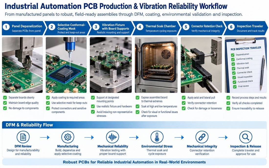
A vibration check is only useful when the fixture supports the board as the enclosure does. Use the actual mounting points, connector retention, cable bend, and support hardware. If thermal cycling is part of the product environment, keep the same coating and enclosure configuration in the sample. A controlled prototype PCB should represent the production panel and depanelization method rather than a hand-cut single board.
Use a traveler that connects DFM to inspection
The assembly traveler should identify board revision, panel revision, coating mask, support hardware, and inspection stages. The assembly fixture should not apply a load at a location that the enclosure does not support. Record depanelization condition, coating coverage, connector retention, and the disposition of any board edge or solder-joint anomaly.
| Risk | Design control | Evidence to retain |
|---|---|---|
| Edge damage | Defined rail, tab, score, and inspection criteria | Panel drawing and first-article photos |
| Component fatigue | Support points, staking, and connector retention | Fixture record and mechanical inspection |
| Coating interference | Datum-based mask and clean service zones | Mask drawing and coverage check |
| Thermal stress | Copper spreader and enclosure contact review | Design target and environmental plan |
Freeze the panel and enclosure contract before volume release
The Industrial Automation PCB purchase release should preserve the approved panel, support, coating, and inspection assumptions.
Before releasing the next lot of an Industrial Automation PCB, freeze the panel rails, fiducials, breakaway method, mounting hardware, coating mask, and service corridor. A board-level change can alter the panel stress or move a connector into a tooling keep-out. Attach the approved PCB manufacturing package and the material assumptions to the purchase release so alternates are reviewed against the same mechanical and environmental intent.
An Industrial Automation PCB repeat build is ready for repeat production when the panel can be built, separated, coated, mounted, serviced, and inspected without changing the intended current paths or mechanical supports. A pilot panel is the practical checkpoint before a high-mix line is committed.
The Industrial Automation PCB handoff is strongest when panel, mechanical, coating, and inspection evidence agree.
Sources: Würth Elektronik assembly, grounding, and connector guidance; Analog Devices industrial design and thermal-interface notes; Qorvo enclosure and signal-integrity references; coating, panelization, connector, and PCB material supplier application data. The diagrams are original conceptual engineering graphics and do not represent a customer measurement or qualification report.
