
As wireless communication, radar systems, satellite technology, autonomous vehicles, and high-speed computing continue to evolve, electronic systems are operating at increasingly higher frequencies. Standard PCB materials may no longer provide the electrical stability required for these applications, making high frequency PCBs an essential solution.
High frequency PCBs are specifically designed to minimize signal loss, maintain controlled impedance, and ensure reliable signal transmission in radio frequency (RF), microwave, and millimeter-wave (mmWave) circuits. They are widely used in industries where electrical performance is just as important as mechanical reliability.
This article explores what high frequency PCBs are, their characteristics, commonly used materials, and the applications that rely on them.
What Is a High Frequency PCB?
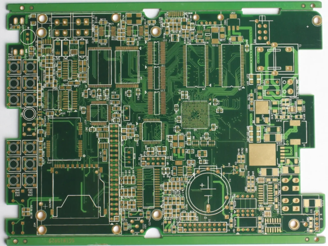
A high frequency PCB is a printed circuit board manufactured using specialized low-loss dielectric materials that maintain stable electrical properties at high operating frequencies.
While conventional FR-4 materials are suitable for many general-purpose electronic products, their dielectric constant (Dk) and dissipation factor (Df) can vary with frequency, resulting in higher signal loss and reduced performance in RF applications.
High frequency PCBs are engineered to provide:
- Stable signal transmission
- Controlled impedance
- Low insertion loss
- Excellent phase stability
- Reduced electromagnetic interference (EMI)
- Consistent electrical performance across a wide frequency range
They are commonly used in circuits operating from several hundred megahertz (MHz) to tens of gigahertz (GHz), and even beyond in advanced mmWave applications.
Key Characteristics of High Frequency PCBs
1. Low Dielectric Loss
One of the most important characteristics of high frequency PCB materials is a low dissipation factor (Df).
Lower dielectric loss helps:
- Reduce signal attenuation
- Improve transmission efficiency
- Maintain stronger RF signals over longer trace lengths
This is particularly important in microwave communication, radar, and high-speed networking equipment.
2. Stable Dielectric Constant (Dk)
The dielectric constant determines how electromagnetic waves propagate through the PCB material.
A stable Dk provides:
- Accurate impedance control
- Predictable signal propagation
- Better phase consistency
- Reduced signal distortion
Materials with minimal Dk variation over temperature and frequency are preferred for high-performance RF designs.
3. Controlled Impedance
Most RF systems require precise impedance matching to minimize signal reflections and maximize power transfer.
Typical controlled impedance values include:
- 50 Ω for RF signal transmission
- 75 Ω for certain communication and video systems
- 100 Ω differential impedance for high-speed digital interfaces
Achieving accurate impedance requires careful control of:
- PCB stack-up
- Trace width
- Copper thickness
- Dielectric thickness
- Material properties
4. Low Signal Loss
At high frequencies, signal attenuation increases rapidly due to conductor and dielectric losses.
High frequency PCB materials help minimize:
- Insertion loss
- Return loss
- Signal reflections
This improves overall communication performance and system efficiency.
5. Excellent Thermal Stability
Many RF and microwave systems operate in demanding environments where temperature changes can affect electrical performance.
High frequency PCB materials typically offer:
- Stable electrical properties across a wide temperature range
- Low coefficient of thermal expansion (CTE)
- Reliable dimensional stability
These properties improve long-term performance and reliability.
6. High Manufacturing Precision
High frequency PCB fabrication requires tighter manufacturing tolerances than standard PCBs.
Critical manufacturing factors include:
- Controlled impedance verification
- Precise etching accuracy
- Consistent dielectric thickness
- Accurate layer registration
- High-quality plated vias
Small manufacturing variations can significantly affect RF performance.
Common Materials Used in High Frequency PCBs
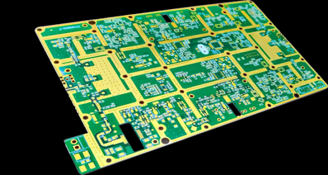
Selecting the appropriate laminate is one of the most important decisions in RF PCB design.
Rogers Materials
Rogers laminates are among the most widely used materials for high-frequency applications due to their stable dielectric properties and low loss.
Common options include:
- Rogers RO4350B™ – Suitable for RF communication, automotive radar, and wireless infrastructure.
- Rogers RO3003™ – Offers excellent phase stability for microwave and satellite applications.
- Rogers RO4835™ – Designed for low-loss, high-frequency communication systems.
PTFE-Based Materials
Polytetrafluoroethylene (PTFE) materials provide:
- Extremely low dielectric loss
- Excellent high-frequency performance
- Stable electrical characteristics
They are commonly used in aerospace, radar, and microwave systems, although they require specialized PCB processing techniques.
Taconic Materials
Taconic laminates offer:
- Low dielectric loss
- Stable dielectric constant
- Good thermal performance
They are widely used in RF, microwave, and high-speed communication products.
Ceramic-Filled Hydrocarbon Materials
These materials combine:
- Improved manufacturability
- Lower moisture absorption
- Enhanced dimensional stability
- Good RF performance
They are often selected for cost-sensitive RF applications.
High Frequency PCB Design Considerations
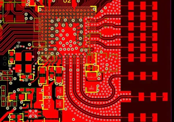
Designing a high frequency PCB requires much more than selecting the right material.
Important design practices include:
Controlled Impedance Routing
Maintaining consistent impedance throughout RF transmission lines helps reduce signal reflections and improve signal integrity.
Short Signal Paths
Keeping RF traces as short as possible minimizes transmission loss and reduces parasitic effects.
Proper Grounding
Continuous ground planes provide stable return current paths and help reduce electromagnetic interference.
Ground via stitching is also commonly used to improve isolation and shielding.
Layer Stack-Up Optimization
A well-designed PCB stack-up improves:
- Impedance consistency
- Signal integrity
- EMI performance
- Crosstalk reduction
Early collaboration between PCB designers and manufacturers is beneficial during stack-up planning.
Thermal Management
High-power RF devices may require:
- Thermal vias
- Thick copper layers
- Heat sinks
- Optimized copper distribution
Effective thermal management helps maintain stable electrical performance.
Typical Applications of High Frequency PCBs
High frequency PCBs are widely used in industries where reliable RF and high-speed signal transmission are essential.
Common applications include:
- 5G base stations
- RF power amplifiers
- Microwave communication systems
- Satellite communication equipment
- Automotive radar (24 GHz and 77 GHz)
- Millimeter-wave (mmWave) devices
- GPS navigation systems
- Wi-Fi routers and wireless networking equipment
- Aerospace and defense electronics
- Medical RF equipment
- Semiconductor test systems
- High-speed data communication equipment
As operating frequencies continue to increase, high frequency PCBs play an increasingly important role in enabling advanced electronic technologies.
Advantages of High Frequency PCBs
Compared with conventional FR-4 PCBs, high frequency PCBs offer several advantages:
- Lower signal transmission loss
- More stable dielectric properties
- Better impedance control
- Higher signal integrity
- Reduced electromagnetic interference
- Improved phase stability
- Better thermal reliability
- Enhanced performance for RF and microwave applications
These benefits make them the preferred choice for demanding communication and high-speed electronic systems.
Conclusion
High frequency PCBs are specifically engineered to support reliable signal transmission in RF, microwave, and high-speed digital applications. Their low-loss materials, stable dielectric properties, and precise manufacturing capabilities help minimize signal degradation while improving overall system performance.
Successful high frequency PCB design depends on more than just choosing the right laminate. Controlled impedance, optimized stack-up, proper grounding, thermal management, and close cooperation between designers and PCB manufacturers are all essential for achieving consistent electrical performance and long-term reliability.
As wireless technologies continue to advance, high frequency PCBs will remain a key foundation for next-generation communication, automotive, aerospace, and industrial electronic systems.
