As RF and microwave systems continue to expand in industries such as 5G communications, automotive radar, satellite equipment, and wireless networking, the choice of PCB material becomes critical. At high frequencies, signal integrity and loss performance can no longer rely on standard FR4.
RO3003 PCB is a popular solution for high-frequency applications because it provides low dielectric loss, stable electrical performance, and consistent impedance control, making it ideal for precision RF circuits.
In this article, we’ll introduce what RO3003 PCB is, its key advantages, common applications, and important manufacturing considerations.
What Is RO3003 PCB?
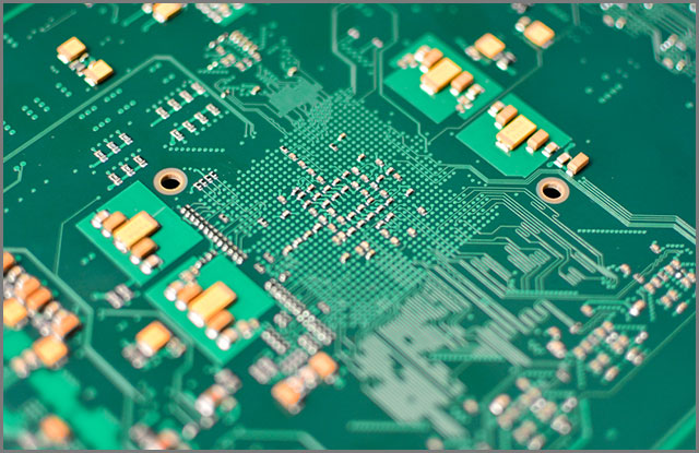
RO3003 PCB refers to a printed circuit board made using Rogers RO3003™ laminate, a high-frequency circuit material engineered for RF and microwave performance.
RO3003 is known for its stable dielectric constant (Dk) and low dissipation factor (Df), which help reduce insertion loss and improve signal consistency at microwave frequencies.
Because of these properties, RO3003 PCB is widely used in designs that require:
-
High frequency stability
-
Low signal attenuation
-
Reliable impedance performance
-
High manufacturing repeatability
Key Benefits of RO3003 PCB
1. Low Dielectric Loss for Better RF Efficiency
One of the most important reasons engineers choose RO3003 PCB is its low loss performance, which helps reduce energy dissipation during signal transmission.
This results in:
-
Lower insertion loss
-
Higher antenna efficiency
-
Improved RF output power consistency
-
Better performance for long trace routing
2. Stable Dielectric Constant (Dk) for Accurate Impedance Control
In RF and microwave circuits, consistent impedance is essential for performance and matching. RO3003 PCB offers stable Dk behavior, which helps achieve:
-
Accurate 50Ω / 75Ω transmission lines
-
Stable phase delay
-
Reduced impedance drift across frequency
This is especially important in antennas, filters, and microwave networks.
3. Excellent Performance at Microwave Frequencies
RO3003 is designed specifically for microwave and high-frequency operation, making it suitable for:
-
RF front-end circuits
-
High-frequency filters and couplers
-
Power amplifiers and LNAs
-
Microwave antennas
4. Good Reliability and Repeatability in Production
Compared with many standard PCB materials, RO3003 PCB is widely recognized for its consistency, which is critical for mass production of RF boards.
This improves:
-
Manufacturing yield
-
Performance repeatability
-
Long-term reliability
Typical Applications of RO3003 PCB
RO3003 PCB is widely used in industries that require stable RF performance.
Antennas and RF Modules
RO3003 is often used in antenna designs such as:
-
Patch antennas
-
Antenna arrays
-
Wireless communication modules
Its low loss properties help improve radiation efficiency and signal quality.
Automotive Radar and ADAS
RO3003 PCB is suitable for high-frequency circuits used in:
-
Radar sensors
-
Vehicle communication systems
-
ADAS modules
Stable performance under environmental stress is essential in automotive electronics.
5G and Telecom Equipment
In telecom applications, RO3003 PCBs can be found in:
-
5G base station RF boards
-
Small cell RF modules
-
High-frequency signal distribution networks
Satellite and Aerospace Systems
For high-reliability RF applications, RO3003 is also used in:
-
Satellite communication modules
-
Aerospace RF systems
-
High-frequency navigation equipment
RO3003 PCB vs FR4: Why Material Selection Matters
FR4 works well for general electronics, but at high frequencies it often causes higher loss and unstable performance.
| Feature | FR4 PCB | RO3003 PCB |
|---|---|---|
| RF Loss | Higher | Lower |
| Dk Stability | Moderate | Excellent |
| High-Frequency Use | Limited | Strong |
| Impedance Control | More difficult | More consistent |
| Typical Applications | General electronics | RF & microwave circuits |
For high-frequency designs, RO3003 PCB offers a clear advantage in performance and reliability.
Manufacturing Considerations for RO3003 PCB
To ensure stable electrical performance, RO3003 PCB manufacturing requires careful process control.
Key considerations include:
Stack-Up and Impedance Planning
RO3003 PCB is often used for controlled impedance RF lines. Proper stack-up planning is essential for:
-
Microstrip / stripline design
-
Dielectric thickness selection
-
Copper thickness control
Precise Etching for RF Trace Accuracy
RF traces are sensitive to width variations. Accurate etching ensures:
-
Consistent impedance
-
Reduced mismatch and reflection
-
Stable RF performance
Surface Finish Selection
Common finishes for RO3003 PCB include:
-
ENIG
-
Immersion Silver
-
OSP
The best choice depends on frequency requirements, assembly process, and reliability targets.
Quality Inspection and Testing
To ensure performance, manufacturers may apply:
-
AOI inspection
-
Controlled impedance testing
-
X-ray inspection (for complex RF structures)
-
Electrical testing
Conclusion
RO3003 PCB is an excellent choice for RF and microwave applications where low loss, stable Dk, and reliable impedance control are critical. It is widely used in antennas, radar, 5G telecom equipment, and satellite communication systems, helping engineers achieve high-performance results with consistent reliability.
If your project requires stable RF performance and low insertion loss, RO3003 PCB is one of the most trusted high-frequency material options available.
