
TLY-5 PCB RF test fixture design is often the hidden variable in a prototype program. A device under test can appear to have excess loss or phase drift when the real variation comes from connector wear, launch geometry, cable movement, or an undefined calibration plane. The fixture must be treated as an RF product with its own stackup, mechanical datum, and evidence package.
Table of Contents
Choose a reference plane the test team can reproduce
Define whether calibration ends at the connector face, launch pad, or DUT edge. The choice affects de-embedding length, torque repeatability, and the amount of fixture included in the result. TLY-5 PCB geometry should use a mechanical datum that is visible to both layout and test. The RF PCB design design record should include cable bend limits, connector gender, torque instruction, and the fixture orientation used for each sweep.
Design the launch for service life, not only first-pass loss
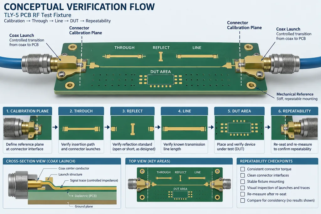
A launch that is excellent on day one may drift after repeated mating. Protect the pad, ground-via fence, solder-mask opening, and connector body from unnecessary rework. TLY-5 PCB transition dimensions should be tied to finished thickness and copper assumptions. The PCB manufacturing manufacturing traveler can add edge plating, counterbore, stiffener, or torque features when the mechanical interface needs them.
Use coupons to separate fixture from DUT behavior
Place a through, line, or back-to-back witness that represents the critical path. The coupon is most useful when its layer pair, finish, and connector footprint match the fixture rather than when it is a generic impedance strip. TLY-5 PCB coupon data should be traceable to the same panel. A RF PCB materials impedance review can then compare a process shift with a fixture shift before the DUT is retuned.
Control calibration workflow and operator handoff
Write the sequence: inspect connector, clean interface, torque, warm-up, calibrate, verify with a known standard, then sweep the DUT. The operator should record cable ID, instrument state, calibration kit, fixture serial, and ambient condition. TLY-5 PCB documentation keeps the reference plane visible; controlled-impedance PCB assembly and inspection notes prevent a repaired connector from being treated as equivalent to a new one.
Release the fixture as a controlled asset
Freeze the stackup, launch drawing, connector part, calibration method, acceptance window, and revision history. Keep a calculated phase budget separate from measured fixture data. TLY-5 PCB test-fixture controls should travel with the board drawing, while PCB assembly production records identify panel, material lot, and any rework. This separation makes a failed correlation actionable instead of anecdotal.
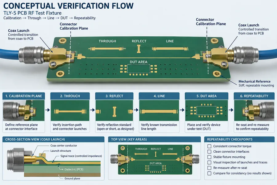
When the fixture, coupon, and DUT share a controlled reference, the engineering team can decide whether a change belongs in the design, fabrication, or measurement chain. That shortens debug cycles and gives program managers a defensible reason to accept or reject a prototype.
Project evidence and handoff for TLY-5 PCB RF test fixture
For a test fixture, the evidence package should identify calibration plane, cable set, connector torque, fixture serial, warm-up time, coupon response, and operator sequence. That record prevents a fixture change from being mistaken for a DUT improvement. The TLY-5 PCB drawing should make the critical datum visible to layout, fabrication, assembly, and test. If a number is calculated, retain the assumptions; if it is a supplier typical, keep it labeled as typical; if it is a measured acceptance value, keep the sample, method, and revision traceable.
| Release item | Engineering question | Evidence to retain |
|---|---|---|
| Stackup and material | Does the finished construction match the RF model? | Finished dielectric target, copper assumption, material lot, cross-section |
| Transition or critical path | Is the mechanical datum also the electrical datum? | Launch drawing, via or pad dimensions, mask and connector inspection |
| Process witness | Does the coupon represent the product feature? | Panel position, layer pair, finish, drill and impedance record |
| Assembly and test | Could placement, rework, or calibration move the result? | Placement tolerance, reflow or rework history, fixture and reference plane |
For program control, use a short disposition statement after each build: what passed, what moved, what is still a target, and which owner decides the next change. This keeps the TLY-5 PCB RF test fixture discussion focused on evidence and prevents a new material, finish, or layout change from being introduced without an updated model and acceptance plan.
For a TLY-5 PCB RF test fixture, retain the TLY-5 PCB connector datum in the calibration record; the TLY-5 PCB fixture drawing should identify the reference plane and board revision used for correlation.
The TLY-5 PCB fixture should use a TLY-5 PCB coupon that shares the launch layer pair and surface finish with the device-under-test board.
This TLY-5 PCB release keeps the TLY-5 PCB calibration record tied to the finished board.
Sources: Taconic and Rogers typical material data; IPC-TM-650 methods relevant to dielectric, copper, drilling, plating, registration, and impedance; RF application guidance from Qorvo, Analog Devices, and Würth Elektronik; KKPCB PCB design, materials, manufacturing, assembly, and high-frequency capability pages. Values are typical, target, or calculated references unless explicitly identified as measured.
