
Taconic RF-35 PCB rework limits should be defined before the first failure, not invented at the bench. Removing a connector, amplifier, or shield can change pad adhesion, solder fillet, local copper, and thermal history. On an RF board, those changes may move the launch or reference plane even when the repaired joint looks acceptable under magnification.
Table of Contents
Classify rework by RF sensitivity
Separate ordinary digital pads from connector launches, filters, transitions, and exposed thermal pads. Taconic RF-35 PCB documentation should mark the RF keep-out and the reference plane most likely to move. The RF PCB design assembly record can then assign different limits for heating cycles, pad lifting, solder removal, and connector replacement.
Control thermal history and board support
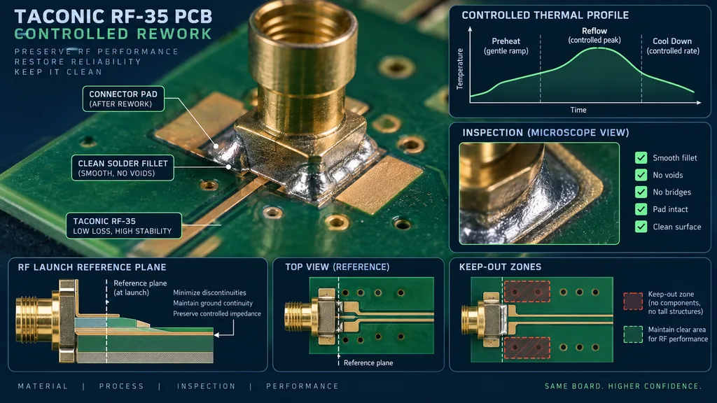
Use a defined profile, local preheat, support tooling, and cleaning method. Excessive dwell can change solder mask, laminate moisture state, or nearby component alignment. Taconic RF-35 PCB stackup assumptions should remain visible when a repair heats one side of the board. The PCB manufacturing manufacturing and assembly handoff should record operator, tool, temperature target, and the reason for rework.
Inspect the pad and launch after repair
Check pad planarity, solder fillet, mask opening, connector coplanarity, voids, and adjacent via fences. A repaired joint should not be treated as equivalent to an untouched joint without evidence. Taconic RF-35 PCB drawings should identify the critical datum. The RF PCB materials controlled-impedance PCB review can compare connector position, coupon condition, and reference-plane continuity after repair.
Separate diagnostic boards from release evidence
A reworked board may be valuable for fault isolation but unsuitable for production correlation. Label the board history and test it with a separate identifier. Taconic RF-35 PCB material and fixture records should show that the sample was reworked. The controlled-impedance PCB RF PCB materials and assembly records should never merge its result into a clean-build capability claim.
Close the loop with post-rework RF checks
Define the minimum sweep, calibration plane, phase or loss limit, and disposition rule. Taconic RF-35 PCB rework controls should distinguish a calculated expectation from a measured result. The PCB assembly release package can then decide whether to accept for debug, quarantine for destructive analysis, or rebuild with a process correction.
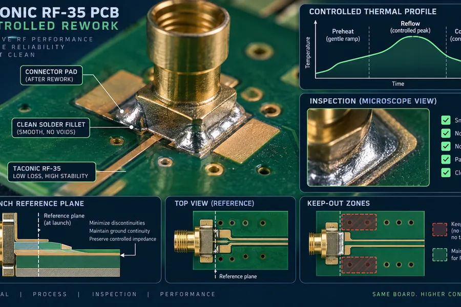
A controlled rework rule protects engineering learning. It tells the team when a board remains useful for diagnosis, when it must be excluded from RF correlation, and when the next build needs a process change rather than another repair.
Project evidence and handoff for Taconic RF-35 PCB rework limits
For a reworked assembly, mark board history, number of heat cycles, replaced part, connector condition, pad inspection, cleaning, and post-rework sweep. A repaired sample can support diagnosis while remaining excluded from a clean-build capability claim. The Taconic RF-35 PCB drawing should make the critical datum visible to layout, fabrication, assembly, and test. If a number is calculated, retain the assumptions; if it is a supplier typical, keep it labeled as typical; if it is a measured acceptance value, keep the sample, method, and revision traceable.
| Release item | Engineering question | Evidence to retain |
|---|---|---|
| Stackup and material | Does the finished construction match the RF model? | Finished dielectric target, copper assumption, material lot, cross-section |
| Transition or critical path | Is the mechanical datum also the electrical datum? | Launch drawing, via or pad dimensions, mask and connector inspection |
| Process witness | Does the coupon represent the product feature? | Panel position, layer pair, finish, drill and impedance record |
| Assembly and test | Could placement, rework, or calibration move the result? | Placement tolerance, reflow or rework history, fixture and reference plane |
For program control, use a short disposition statement after each build: what passed, what moved, what is still a target, and which owner decides the next change. This keeps the Taconic RF-35 PCB rework limits discussion focused on evidence and prevents a new material, finish, or layout change from being introduced without an updated model and acceptance plan.
Sources: Taconic and Rogers typical material data; IPC-TM-650 methods relevant to dielectric, copper, drilling, plating, registration, and impedance; RF application guidance from Qorvo, Analog Devices, and Würth Elektronik; KKPCB PCB design, materials, manufacturing, assembly, and high-frequency capability pages. Values are typical, target, or calculated references unless explicitly identified as measured.
