
With the rapid development of wireless communication technologies, microstrip patch antennas have become widely used in applications such as 5G communication systems, satellite communication, radar equipment, IoT devices, automotive electronics, and wearable devices.

Compared with traditional antenna structures, microstrip patch antennas offer advantages including low profile, lightweight construction, easy integration with PCB circuits, and suitability for mass production. However, their performance is highly dependent on design parameters and manufacturing conditions.
Factors such as substrate material selection, dielectric properties, antenna geometry, feeding structure, and fabrication accuracy can significantly influence important antenna characteristics, including:
- Resonant frequency
- Bandwidth
- Gain
- Radiation efficiency
- Impedance matching
- Polarization performance
Understanding these influencing factors is essential for developing reliable RF systems with stable antenna performance.
1. Substrate Material Properties
The PCB substrate is one of the most important factors affecting microstrip patch antenna performance.
The dielectric characteristics of the substrate directly influence electromagnetic wave propagation and antenna behavior.Dielectric Constant (Dk)
The dielectric constant determines the effective wavelength of the RF signal inside the substrate.
A higher dielectric constant generally results in:
- Smaller antenna size
- Reduced wavelength
- Increased dielectric losses
- Narrower bandwidth
A lower dielectric constant can provide:
- Higher radiation efficiency
- Wider bandwidth
- Better antenna performance
However, the antenna size will typically increase.
Therefore, designers must balance size requirements and RF performance when selecting substrate materials.
Dielectric Loss Tangent (Df)
The loss tangent represents energy loss within the dielectric material.
A lower loss tangent helps achieve:
- Higher radiation efficiency
- Lower signal attenuation
- Improved antenna gain
For high-frequency applications such as microwave communication and mmWave systems, low-loss materials are often preferred.
Common RF substrate materials include:
- Rogers RO3003™
- Rogers RO4350B™
- Rogers RO4835™
- PTFE-based laminates
- Taconic high-frequency materials
Substrate Thickness
The thickness of the dielectric layer affects antenna bandwidth and impedance characteristics.
Increasing substrate thickness may:
- Increase bandwidth
- Improve radiation efficiency
However, excessive thickness can introduce:
- Surface wave losses
- Higher spurious radiation
- Reduced impedance stability
Selecting the appropriate substrate thickness is critical for achieving the desired antenna performance.
2. Patch Antenna Geometry Design
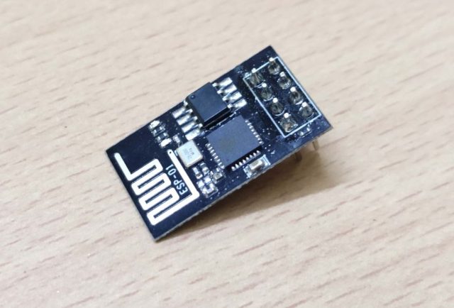
The physical dimensions and shape of the patch strongly affect antenna operation.
Patch Length and Width
The patch dimensions determine the resonant frequency.
A longer patch generally lowers the resonant frequency, while a shorter patch increases it.
The patch width influences:
- Radiation efficiency
- Input impedance
- Bandwidth characteristics
Accurate calculation and simulation are required to achieve the target operating frequency.
Patch Shape
Although rectangular patches are most common, different shapes can be used to optimize performance.
Common patch geometries include:
- Rectangular patches
- Circular patches
- Square patches
- Ring-shaped patches
- Array structures
Different shapes influence:
- Radiation patterns
- Bandwidth
- Polarization characteristics
3. Feeding Technique
The feeding structure determines how effectively RF energy is transferred between the transmission line and antenna.
Common feeding methods include:
Microstrip Line Feed
Advantages:
- Simple structure
- Easy PCB integration
- Low manufacturing cost
Limitations:
- May introduce unwanted radiation
- Limited bandwidth
Coaxial Probe Feed
Advantages:
- Good impedance matching capability
- Flexible feeding position adjustment
Limitations:
- More difficult fabrication for thin substrates
- Requires precise drilling
Aperture Coupled Feed
Advantages:
- Improved isolation between antenna and feed network
- Wider bandwidth capability
Limitations:
- More complex multilayer PCB structure
Proximity Coupled Feed
Advantages:
- Higher bandwidth
- Better impedance matching performance
Limitations:
- More complicated manufacturing process
4. Ground Plane Design
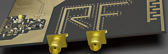
The ground plane plays an important role in controlling antenna radiation characteristics.
Important factors include:
- Ground plane size
- Ground continuity
- Ground layer structure
An insufficient ground plane may cause:
- Frequency shift
- Reduced gain
- Distorted radiation patterns
A well-designed ground structure improves:
- Current distribution
- Radiation efficiency
- Antenna stability
For PCB antennas, maintaining proper grounding and return current paths is essential.
5. Operating Frequency and Bandwidth Requirements
Microstrip patch antennas usually have relatively narrow bandwidth compared with other antenna types.
Bandwidth can be influenced by:
- Substrate thickness
- Dielectric constant
- Patch geometry
- Feeding method
- Antenna array configuration
For applications requiring wider bandwidth, designers may use techniques such as:
- Stacked patch structures
- Slot designs
- Multiple resonators
- Array antennas
6. Manufacturing Accuracy and PCB Fabrication Factors
Even a well-designed antenna can experience performance degradation due to manufacturing variations.
Important PCB manufacturing factors include:
Dielectric Thickness Variation
Changes in dielectric thickness can affect:
- Impedance
- Resonant frequency
- Antenna matching
Copper Thickness Variation
Copper thickness influences conductor loss and current distribution.
Etching Tolerance
Variation in trace width and patch dimensions can cause:
- Frequency deviation
- Reduced matching performance
Layer Alignment Accuracy
For multilayer antenna structures, misalignment may affect:
- Coupling performance
- Radiation characteristics
- Signal consistency
Therefore, close cooperation between antenna designers and PCB manufacturers is necessary to ensure production reliability.
7. Environmental Effects
Microstrip patch antennas may operate under different environmental conditions, which can influence performance.
Temperature Variation
Changes in temperature may affect:
- Dielectric properties
- Resonant frequency
- Impedance matching
Humidity and Moisture
Moisture absorption can change substrate characteristics and increase dielectric losses.
For outdoor or automotive applications, environmental reliability should be considered during material selection.
8. Simulation and Testing Considerations
Before mass production, antenna performance should be verified through simulation and testing.
Electromagnetic Simulation
Simulation tools help evaluate:
- Current distribution
- Radiation patterns
- Gain
- Return loss
- Impedance matching
Common simulation methods include:
- Finite Element Method (FEM)
- Finite Difference Time Domain (FDTD)
RF Testing
Practical testing may include:
- Vector Network Analyzer (VNA) measurement
- S-parameter testing
- Radiation pattern measurement
- Gain testing
These measurements help confirm that the fabricated antenna meets design requirements.
9. Applications of Microstrip Patch Antennas
Microstrip patch antennas are widely used in:
- 5G communication equipment
- GPS modules
- Wi-Fi devices
- Bluetooth products
- Automotive radar systems
- Satellite communication
- IoT sensors
- Medical wireless devices
- Wearable electronics
Their compact structure and PCB compatibility make them an important technology for modern wireless systems.
Conclusion
The performance of microstrip patch antennas depends on the interaction between electromagnetic design, material characteristics, PCB structure, and manufacturing accuracy.
Key factors affecting antenna performance include:
- Substrate dielectric properties
- Patch geometry
- Feeding method
- Ground plane design
- Manufacturing tolerances
- Environmental conditions
By carefully optimizing these factors and combining accurate simulation with reliable PCB fabrication processes, engineers can achieve improved antenna efficiency, stable frequency response, and better overall RF system performance.

