
Mounting holes are an essential but often overlooked part of PCB design. While most engineers focus on electrical performance, component placement, and signal integrity, the mechanical connection between a PCB and its enclosure, chassis, or other assemblies can significantly affect product reliability.
One of the key decisions during PCB design is whether to use plated through holes (PTH) or non-plated through holes (NPTH) for mechanical mounting.
Although both options serve the purpose of securing the PCB, they have different manufacturing processes, costs, and application considerations.
Choosing the right mounting hole type can help improve:
- Mechanical stability
- Assembly efficiency
- Manufacturing reliability
- Product lifetime
This article explains the differences between plated and unplated PCB mounting holes and provides guidance on selecting the appropriate solution for different applications.
What Are PCB Mounting Holes?
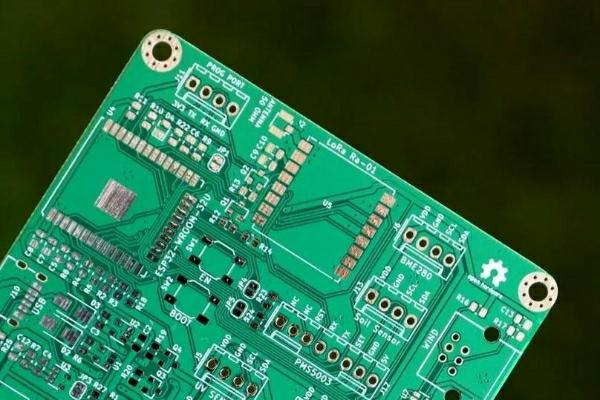
PCB mounting holes are drilled openings designed to mechanically attach a circuit board to:
- Product enclosures
- Metal frames
- Mechanical supports
- Heat sinks
- Other PCB assemblies
Unlike vias, mounting holes are primarily intended for mechanical purposes rather than electrical connections.
However, depending on the design requirements, mounting holes can also provide:
- Grounding connections
- Shielding connections
- Chassis bonding
The two main types are:
- Plated Through Holes (PTH)
- Non-Plated Through Holes (NPTH)
What Is a Plated Through Hole (PTH)?
A plated through hole is a drilled hole with a copper layer deposited on the inner wall.
During PCB manufacturing, the hole undergoes copper plating, creating an electrical connection between different conductive layers.
Characteristics of PTH Mounting Holes
A plated mounting hole provides:
- Mechanical attachment
- Electrical conductivity
- Ground connection capability
Typical applications include:
- Chassis grounding
- Shielding connections
- Metal screw mounting points
- High-reliability industrial equipment
Advantages of Plated PCB Mounting Holes
1. Electrical Grounding Capability
One of the biggest advantages of PTH mounting holes is their ability to provide electrical connections.
For example, a mounting hole connected to the PCB ground plane can create:
- Chassis grounding
- EMI shielding improvement
- Reduced electromagnetic interference
This is particularly useful in:
- Industrial control systems
- RF equipment
- Power electronics
2. Improved Mechanical Reliability
The copper plating around the hole provides additional reinforcement.
Benefits include:
- Stronger connection points
- Better resistance to mechanical stress
- Improved durability during repeated assembly
This is valuable for products exposed to:
- Vibration
- Shock
- Temperature cycling
3. Better Compatibility with Metal Hardware
When screws, standoffs, or conductive spacers are used, plated holes provide reliable contact between:
- PCB ground layers
- Mounting hardware
- Product chassis
This helps improve system-level reliability.
Disadvantages of Plated Through Holes
Despite their advantages, PTH mounting holes also have some limitations.
1. Higher Manufacturing Cost
Additional manufacturing steps are required:
- Hole drilling
- Desmear process
- Copper plating
- Inspection
These processes increase production complexity and cost.
2. Potential Reliability Concerns
Poor plating quality may cause:
- Uneven copper thickness
- Cracks under mechanical stress
- Reduced reliability
Therefore, proper manufacturing control is required.
What Is a Non-Plated Through Hole (NPTH)?
A non-plated through hole is simply a drilled hole without copper plating on the inner wall.
The hole provides only mechanical functionality.
Common examples include:
- Screw mounting holes
- Positioning holes
- Mechanical alignment holes
Advantages of Unplated PCB Mounting Holes
1. Lower Manufacturing Cost
NPTH holes require fewer processes compared with plated holes.
Advantages include:
- Simpler fabrication
- Lower production cost
- Faster manufacturing cycle
For designs where electrical connection is unnecessary, NPTH is usually the preferred choice.
2. Better Mechanical Isolation
Because NPTH holes are electrically isolated, they prevent unwanted connections between:
- Screws
- Chassis components
- PCB copper layers
This can be beneficial when electrical isolation is required.
3. Suitable for Standard Mechanical Assembly
NPTH holes are commonly used for:
- Plastic screws
- Nylon spacers
- Mechanical supports
- PCB positioning
They provide reliable physical mounting without adding unnecessary electrical complexity.
Disadvantages of Unplated Through Holes
1. No Electrical Connection
The biggest limitation is that NPTH holes cannot provide:
- Ground connection
- Signal connection
- Shielding connection
If grounding is required, additional design methods are needed.
2. Reduced Mechanical Strength Compared with PTH
Because there is no copper reinforcement, NPTH holes may have slightly lower mechanical strength in certain applications.
For most standard assemblies, however, this difference is minimal.
Plated vs Unplated PCB Mounting Holes Comparison
| Feature | Plated Through Hole (PTH) | Non-Plated Through Hole (NPTH) |
|---|---|---|
| Electrical connection | Yes | No |
| Mechanical mounting | Excellent | Excellent |
| Manufacturing cost | Higher | Lower |
| Grounding capability | Available | Not available |
| EMI shielding support | Possible | Limited |
| Process complexity | Higher | Lower |
| Common applications | Industrial, RF, power systems | Standard mechanical mounting |
How to Choose Between PTH and NPTH?
The correct choice depends on the electrical and mechanical requirements of the product.
Choose PTH When:
Use plated mounting holes if the design requires:
- Chassis grounding
- EMI control
- Shielding connection
- Conductive mechanical structures
- High mechanical reliability
Examples:
- Industrial controllers
- Power converters
- Communication equipment
- Automotive electronics
Choose NPTH When:
Use unplated mounting holes if the requirement is only mechanical mounting.
Suitable applications include:
- Consumer electronics
- Plastic enclosure products
- Standard control boards
- Cost-sensitive products
PCB Design Considerations for Mounting Holes
1. Maintain Proper Clearance
Engineers should consider clearance between:
- Mounting holes
- Copper traces
- Components
- Ground planes
Incorrect clearance may cause:
- Short circuits
- Assembly problems
- Mechanical interference
2. Consider Screw and Hardware Selection
The hole design should match:
- Screw diameter
- Washer size
- Standoff structure
- Assembly method
Common mounting hardware includes:
- Metal screws
- Plastic screws
- Spacers
- Rivets
3. Consider Mechanical Stress
Mounting areas experience mechanical forces during:
- Installation
- Transportation
- Operation
For high-stress environments, engineers should evaluate:
- Hole size
- Copper reinforcement
- Keep-out zones
- Board thickness
Manufacturing Considerations
From a PCB manufacturing perspective, mounting hole requirements should be clearly defined in the design files.
Important information includes:
- Hole diameter
- Plated or unplated specification
- Tolerance requirements
- Mechanical layer definition
Incorrect definition may result in:
- Manufacturing delays
- Additional costs
- Assembly issues
A professional PCB manufacturer will review mounting hole requirements during DFM analysis to ensure manufacturability.
Conclusion
The decision between plated and unplated PCB mounting holes depends on whether the hole needs to provide electrical functionality in addition to mechanical support.
Plated through holes (PTH) are suitable when grounding, EMI control, or enhanced mechanical reliability is required.
Non-plated through holes (NPTH) are ideal for simple mechanical mounting where electrical connection is unnecessary.
By selecting the appropriate mounting hole structure during PCB design, engineers can achieve a better balance between:
- Cost
- Reliability
- Manufacturing efficiency
- Product performance
Early DFM review with an experienced PCB manufacturer can help identify the most suitable mounting hole solution before production, reducing potential manufacturing risks and improving final product quality.
