
With the rapid development of advanced driver assistance systems (ADAS) and autonomous driving technologies, automotive radar has become one of the most important sensing technologies for modern vehicles.
Compared with traditional automotive sensors, radar systems provide advantages such as:
- all-weather operation,
- long detection range,
- strong environmental adaptability,
- reliable object detection.
However, automotive radar design involves complex RF engineering challenges. As operating frequencies increase and systems require higher resolution, engineers must carefully consider:
- RF signal integrity,
- antenna performance,
- material selection,
- impedance control,
- electromagnetic compatibility (EMC),
- thermal reliability.
From an RF PCB design perspective, automotive radar is not only a circuit design challenge but also a manufacturing and reliability challenge.
What Is Automotive Radar?
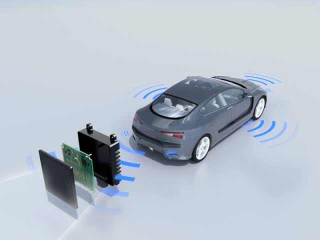
Automotive radar is a sensing system that uses electromagnetic waves to detect surrounding objects and measure:
- distance,
- speed,
- direction,
- relative movement.
Most automotive radar systems operate in the millimeter-wave frequency range, including:
- 24 GHz radar,
- 77 GHz radar,
- 79 GHz radar.
Among them, 77/79 GHz radar has become increasingly common due to its:
- higher bandwidth,
- better resolution,
- smaller antenna size.
Typical applications include:
- adaptive cruise control (ACC),
- blind spot detection (BSD),
- automatic emergency braking (AEB),
- lane change assistance,
- autonomous driving perception systems.
Key RF Design Challenges in Automotive Radar
1. High-Frequency Signal Integrity
Automotive radar operates at extremely high frequencies, where even small PCB variations can affect signal performance.
At millimeter-wave frequencies, factors such as:
- transmission loss,
- dielectric variation,
- copper roughness,
- impedance fluctuation,
can significantly impact RF performance.
Potential issues include:
- reduced detection range,
- inaccurate object measurement,
- increased signal attenuation.
Better Approach:
RF PCB design should focus on:
- controlled impedance routing,
- optimized transmission line structures,
- short RF signal paths,
- consistent dielectric properties.
Simulation and verification are important before production to ensure stable RF performance.
2. RF Material Selection
Unlike conventional digital PCBs, automotive radar boards require specialized high-frequency materials.
Common RF PCB materials include:
- PTFE-based laminates,
- Rogers materials,
- low-loss hydrocarbon ceramic laminates.
Material selection affects:
- dielectric constant stability,
- insertion loss,
- phase performance,
- temperature reliability.
Key Material Parameters:
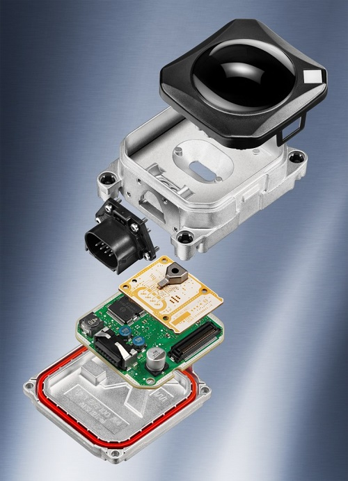
Engineers should consider:
- low dielectric loss tangent,
- stable Dk value,
- low moisture absorption,
- suitable thermal expansion characteristics.
For automotive environments, material reliability under temperature cycling is especially important.
3. Antenna Integration and Layout Design
The antenna is one of the most critical components in automotive radar systems.
PCB antenna design directly influences:
- detection distance,
- beam pattern,
- angular accuracy.
Important considerations include:
- antenna geometry,
- spacing between antenna elements,
- ground plane design,
- RF feeding structure.
Poor antenna integration may result in:
- signal distortion,
- reduced sensitivity,
- incorrect target detection.
Better Approach:
RF engineers should optimize:
- antenna layout,
- transmission line transition,
- impedance matching,
- electromagnetic simulation.
4. Impedance Control
At millimeter-wave frequencies, impedance control becomes extremely sensitive.
Small manufacturing variations in:
- trace width,
- copper thickness,
- dielectric thickness,
- surface roughness,
may cause impedance deviation.
Common target impedance:
- 50Ω RF transmission lines.
PCB Manufacturing Considerations:
To maintain RF performance, manufacturers need strict control of:
- stackup structure,
- copper etching accuracy,
- material tolerance,
- surface finish.
Advanced testing methods such as TDR analysis can help verify impedance consistency.
5. Electromagnetic Compatibility (EMC) Design
Automotive radar systems operate in complex electromagnetic environments.
They must coexist with:
- vehicle electronics,
- communication modules,
- power systems.
Poor EMC design can lead to:
- unwanted interference,
- unstable radar signals,
- reduced system accuracy.
EMC Optimization Methods:
Engineers should consider:
- proper grounding strategy,
- shielding structures,
- controlled return paths,
- optimized power filtering.
Reducing electromagnetic interference (EMI) is essential for reliable radar operation.
6. Thermal Management
Automotive radar modules often operate continuously under harsh conditions.
Challenges include:
- high ambient temperature,
- compact enclosure,
- limited heat dissipation.
Heat sources include:
- RF transceiver chips,
- processors,
- power management components.
Thermal Design Solutions:
Effective approaches include:
- thermal vias,
- copper heat spreading,
- optimized component placement,
- suitable substrate selection.
Good thermal management improves:
- component lifetime,
- signal stability,
- system reliability.
7. Automotive Reliability Requirements
Automotive electronics must withstand demanding environments, including:
- temperature cycling,
- vibration,
- humidity,
- mechanical stress.
Radar PCBs require:
- high material reliability,
- robust solder joints,
- stable electrical performance.
Manufacturing considerations include:
- reliable PCB lamination,
- precise drilling,
- high-quality surface finishing,
- strict inspection processes.
PCB Manufacturing Considerations for Automotive Radar
High-Precision PCB Fabrication
Automotive radar PCBs often require:
- multilayer structures,
- fine-line routing,
- controlled impedance,
- advanced materials.
Manufacturing accuracy directly affects RF performance.
Surface Finish Selection
Surface finish influences:
- signal transmission loss,
- solder reliability,
- long-term durability.
Common options include:
- ENIG,
- ENEPIG.
For high-frequency applications, surface treatment consistency is critical.
Advanced Testing
Automotive radar PCB validation may include:
- impedance testing,
- RF performance testing,
- dimensional inspection,
- environmental reliability testing.
These processes help ensure stable mass production.
Future Trends in Automotive Radar Technology
Higher Frequency Radar
Future radar systems are moving toward:
- higher bandwidth,
- improved resolution,
- smaller antenna structures.
Integration with AI and Sensor Fusion
Radar systems will increasingly combine with:
- cameras,
- LiDAR,
- AI processors.
This requires even higher-performance PCB solutions.
Miniaturized Radar Modules
Future automotive radar designs will focus on:
- smaller size,
- higher integration,
- improved thermal efficiency.
Advanced PCB technologies such as:
- HDI,
- RF multilayer PCB,
- embedded components,
will become increasingly important.
Conclusion
Automotive radar design requires close integration between RF engineering, PCB technology, and manufacturing capability.
Key design considerations include:
- RF signal integrity,
- high-frequency material selection,
- antenna optimization,
- impedance control,
- EMC performance,
- thermal management,
- automotive reliability.
As vehicles move toward higher levels of automation, high-performance RF PCB design and manufacturing will play a critical role in enabling safer and more reliable automotive radar systems.
